Powered by Al-driven algorithms, it automatically analvzes end-face imperfections, making it a critical tool for ensuring the reliability of CPO systems-supporting eficient data center operations and smarter future network infrastructure. • Additional connections for foot activation pedal & backplane handset extension. CleanBlastPRO™ is VIAVI's newest automated fiber end-face cleaning system, designed for seamless deployment by component and connectivity manufacturers and integrators. It ensures clean fiber connectors across. AFL offers a complete selection of compact fiber optic cleaning kits for field cleaning of connector end-faces and splicer v-grooves. We offer pre-stocked kits with a variety of cleaning tools and can also build you custom kits to meet your specific application needs. With a variety of kit options. Fiber connectors are precision components designed to carry light signals with minimal loss. Any debris, residue, or static can: Scatter or block light, leading to insertion loss. Create back reflections, which degrade signal quality. Scratch or pit the end face, causing permanent damage. Its large-field-of-view (FOV)design ensures full-core coverage in a single scan, while ultra-high-resolution optics accurately detect micron-level defects. Automated cleaners use a high-speed air/fluid mixture to flush contaminants from the endface, ensuring thorough, consistent cleaning. Fiber-optic technology has become the.
[PDF]
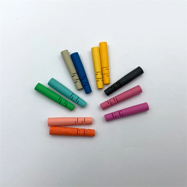
Quick Clean cleaning tool 1. Depending on which kit you purchase, there are different types of Quick Clean cleaning tools included. Each is made with a proprietary lint-free cleaning strand to ensure you.
[PDF]
This precision cleaner quickly cleans the end faces of fiber optic connectors, while eliminating electrostatic charge, which can attract airborne contaminants to the end face. Talk to a knowledgeable OCC Expert that can find or customize a product to fit your specifications. . Chemtronics is the industry leader for fiber optic cleaning products, providing performance, convenience, time savings and cost savings. Cleaning fiber optic connectors is fast, easy and reliable with our highly engineered solvents, lint-free swabs, precision wipes, and cleaning platforms. AFL offers a complete selection of compact fiber optic cleaning kits for field cleaning of connector end-faces and splicer v-grooves. Fluke Networks Fiber Optic Cleaning Kits contain the best fiber optic cleaning tools and products to effectively remove the toughest contaminants in any optical fiber cable (OFC) network. 800-622-7711. Specialized Products provides a variety of optical fiber, end face and splice prep kits from leading fiber optics brands including Sticklers, Chemtronics, AFL and Fluke Networks. These kits are designed to include everything the fiber technician may need while working in the field.
[PDF]

This guide covers everything: what fiber optic pigtails are, how they differ from patch cords, which connector and polish type to specify, how to choose between mechanical and fusion splicing, and the real-world applications where pigtails are the right call. In this guide, we cover the basics of fiber optic splicing, how to perform splicing using two different methods, and finally some best practices to perform good fiber splicing. What is Fiber Optic Splicing and Why is it Needed? – #1. Whether you're building out an ODF. Think of a fiber optic cable splice as the seamless stitching that keeps data flowing through the delicate threads of a network—like a master tailor joining fabric with precision. Whether repairing a broken cable or extending a fiber run, fiber optic splicing ensures light signals travel. Fibre optic splicing is an essential skill in the world of modern telecommunications, offering a reliable method to connect optical fibres for seamless data transmission. As the demand for high-speed internet and robust communication networks continues to grow, learning to splice fibre optics is. In this guide, you will find a chronological description of the fusion splicing process, the principal technical standards, and answers to the real-life questions network engineers and procurement teams may have. Therefore, we will also touch on cost factors, risk management, and best practices in.
[PDF]
In a fused fiber splitter, the input fiber is aligned with the fused region, which causes the optical power to be divided between the output fibers. The tapering process gradually guides the light from the input fiber to the output fibers, resulting in a proportional split of the. A fiber-optic splitter, also known as a beam splitter, is based on a quartz substrate of an integrated waveguide optical power distribution device, similar to a coaxial cable transmission system. The optical network system uses an optical signal coupled to the branch distribution. It plays a crucial role in enabling multiple devices to share a single fiber optic connection, maximizing the utilization of the available. Essentially, a fiber optic splitter performs the following actions: Light Enters: Light travelling through a fiber optic cable enters the splitter. Passive Separation: Inside the splitter, the light is split into multiple separate beams using optical components. Conversely, it can also combine multiple signals into one. Its primary role is in Passive Optical Networks (PON), which are the foundation of. A fiber optic splitter is a passive optical component that divides a single incoming optical signal into two or more outgoing signals, or combines multiple incoming signals into one. However, modern splitters can have multiple inputs and outputs, allowing for the distribution of a single signal to dozens of receivers. The internal workings of a passive.
[PDF]

This video goes over common types of connectors, their respective adapters, and how to properly connect and disconnect them. more Are you interested in seeing how fiber optic connectors get. Unplugging a fiber jack, also known as a fiber optic connector, is a delicate process that requires attention to detail and proper handling to ensure the integrity of the fiber optic cables and connectors. Fiber optics are used in a variety of applications, including telecommunications, internet. If you're wondering how to remove fiber optic cable from connectors, there are a few different ways to do it. You need to know which connector is the correct one for the cable and what kind of wire it's made of. You can also use shears or wire cutters to cut through the connector. This article. Fiber optic connectors are essential components in fiber optic networks, providing a reliable connection between cables and equipment. Removing these connectors requires care to avoid damaging the delicate fibers or the connector itself. To connect a fiber optic cable to SFP optical module, first ensure the SFP is fully inserted into the network port until it "clicks", then remove the dust caps from both the SFP and the LC fiber optic connector.
[PDF]
Fiber Internet Hardware: Quick Answer Fiber internet does not use a traditional cable modem. Instead, it requires an Optical Network Terminal (ONT) — a device supplied by your fiber provider that conve.
[PDF]
Yes. Standard scissors and a ruler will be adequate in most cases, unless you require an exact length of tubing, in which case use a more precise measuring tool. For thicker tubing you may require wire cutt.
[PDF]
Fiber testing is the process of verifying the performance of optical fiber cabling. This process includes a range of tests and measurements such as insertion loss, optical return loss, and fiber length. It encompass.
[PDF]

Compared to conventional metallic cables, optical fiber provides an advantage of low loss (~ 0. 2dB/km) and wide bandwidth (several hundred MHz to THz) to enable long-distance, high-capacity communication. Fiber-optic communication is a form of optical communication for transmitting information from one place to another by sending pulses of infrared or visible light through an optical fiber. The light is a form of carrier wave that is modulated to carry information. Fiber is preferred. It was almost a century later before optical-based communication was put to practical use, thanks in large part to the invention of optical fiber and lasers. A laser's stable, highly directional beam of light (emitted from tiny semiconductor windows that measure just a few hundred thousandths of a. In 2020, we celebrated the 50th anniversary of the invention of low-loss optical fiber — an innovation that has transformed the way we connect and that lies at the cornerstone of our communications revolution. In a Corning lab on a Friday afternoon five decades ago, a single strand of glass and a. Fibre optics and optical communications is the use of thin strands of glass for sending information encoded into light over long distances. Total internal reflection prevents light inserted into one end of the fibre from escaping through the sides. Transferring information optically in this way.
[PDF]

Calculate end-to-end loss from cable length, connector and splice counts, and known component losses; verify with a light source + power meter (OLTS). If installed loss exceeds design, reduce connection points, rework poor splices, or use optics with better. This document presents a troubleshooting guide for fiber optic cables once deployed and in regular use. It also includes a list of common fault location items. How to troubleshoot: measure. Fiber optic networks are celebrated for their speed and reliability, but even the best systems can encounter problems. When issues like signal loss, slow speeds, or intermittent connectivity arise, systematic troubleshooting is key. These high-speed, high-capacity communication networks are increasingly replacing copper cables, offering superior performance and. Fiber optic troubleshooting is the systematic process of identifying, diagnosing, and resolving problems within fiber optic communication networks. These networks are the backbone of modern data transmission, offering incredible speeds and bandwidth. However, even the most robust systems can. Fiber optic cables are the backbone of today's high-speed communication networks, powering everything from FTTH broadband to data centers. However, like any technology, fiber optic systems can encounter issues that affect performance. Understanding the common causes and solutions helps maintain.
[PDF]
Picking up the best router for fiber internet isn't just about going to the market and choosing one of the best wireless routers. Instead, you need to carefully look at its specs, performance, and the type of securit.
[PDF]
In the single mode vs. multimode fiber debate, there is not one cable that's the best, but there are some that are better suited to certain situations. If you need to run fiber optic cable over a vast distance, there's.
[PDF]