Within data centers, optical distribution boxes manage fiber connections between servers, switches, and storage devices. They enable high-density fiber management, reducing cable clutter and improving airflow. This use-case enhances data transfer speeds and system uptime. They protect delicate fiber cables from environmental factors like moisture, dust, and physical damage. These boxes are used in various settings, including outdoor street cabinets. Optical fiber distribution box (often referred to as optical fiber distribution box or ODF box) plays a crucial role in optical fiber networks, and its advantages are mainly reflected in the following aspects: First, efficient fiber management Modular design: The optical fiber distribution box. These boxes simplify network expansion and reduce installation complexity by combining fiber distribution and signal splitting functions in one enclosure. FDB is used for the purpose of distributing and terminal connection to numerous types of optical fiber systems. They are commonly used by FTTH clients wiring equipment, in order to provide protective connections. The box is compact, light and is widely used for end termination of villas and. An Optical Distribution Frame (ODF) is a specialized enclosure designed to manage, connect, protect, and distribute fiber optic cables in telecom and data networks. It acts as a central point for terminating, splicing, and distributing these cables, providing necessary protection and.
[PDF]

Single-mode optical splitters are optimized for single-mode optical fiber, while multimode optical splitters are tailored for use with multimode optical fiber. An Optical Splitter, also known as a beam splitter, is a passive optical device that divides a single input optical signal into two or more output signals. Conversely, it can also combine multiple signals into one. Its primary role is in Passive Optical Networks (PON), which are the foundation of. This guide demystifies fiber optic splitters, explaining their design, operating principles, types, key specifications, and real-world applications. It can distribute the optical energy transmitted through a single fiber to two or more fibers in a predetermined ratio or combine the optical energy from multiple fibers into one fiber. “Passive” means it needs no. You use optical couplers and splitters to split or join signals in fiber networks. For example, optical splitters send light to many output ports. This lets you connect more users to one network terminal. There are different types of fiber optic splitters available, with two of the most common being Fused Biconical Tapered (FBT) splitters and Planar Lightwave.
[PDF]

Single fiber modules (BiDi) use one fiber for both transmitting and receiving data. This saves space and money. They are easier to set up and give steady communication. They use a thin fiber. Pioneer LX305 only has 1 optical input, can I add another with some kind of splitter? I love my new receiver but I need a second optical input and I'm wondering what my options are in this regard. Can anyone help? Thanks in advance. Edit: Everyone is going to ask this question, so here are my. The single-mode optical fiber is designed and engineered to carry one single light mode in a minimal core diameter. It is specified as the best for especially long-distance applications than multimode fiber. Due to its. The optical module serves as a crucial component in optical fiber communication systems, operating at the physical layer, which is the lowest layer in the OSI model. Its primary function is to achieve optoelectronic conversion by converting electrical signals into optical signals and vice versa. An. There are single-fiber and dual-fiber optical transceivers. How do we choose, and what are their differences and advantages? Let's learn about this! What is a Single-Fiber (BiDi) Transceiver? Single fiber module also called BiDi transceiver or WDM module.
[PDF]

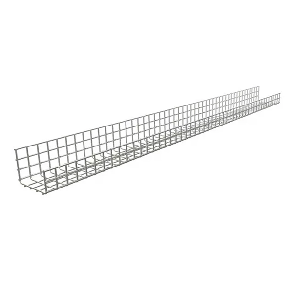
The most common materials used for cable tray production are galvanized steel, stainless steel, and aluminum. Galvanized steel offers a cost-effective solution with good corrosion resistance. Stainless steel provides superior corrosion protection, making it suitable for harsh. A typical cable tray production line encompasses several key stages. These coils are then uncoiled and flattened through a leveling machine. Next, the material is slit to the required width for the tray. Selecting the right raw material for cable trays is vital to maintaining structural integrity, longevity, and cost efficiency. This article dives into the nuances of cable trays raw material, analyzing market trends, cost control strategies, and material innovations. The choice of raw material for. The production process of cable tray manufacturers usually includes the following main steps: Raw material preparation: The main raw materials for cable trays are usually stainless steel, galvanized steel plates, aluminum alloys, etc. It's strong, durable, and can withstand a lot of wear and tear.
[PDF]

Mainly 9steps: Step 1: cut cable with cutting machines in lengths Step 2: put the connector spare parts on the cable Step 3: Strip cable jacket, coating till bare fiber, and make all parts in ready Step 4: Insert fiber into ferrule, glue dispenser and heat oven Step 5:. Mainly 9steps: Step 1: cut cable with cutting machines in lengths Step 2: put the connector spare parts on the cable Step 3: Strip cable jacket, coating till bare fiber, and make all parts in ready Step 4: Insert fiber into ferrule, glue dispenser and heat oven Step 5:. Learn how to make a fiber optic patch cord step by step, from preparation to testing, for reliable high-performance connections. Most guides on making fiber optic patch cord 1 s feel incomplete. They often focus on the final assembly steps, leaving the foundational stages a mystery. From cable cutting to connector assembly and testing, you will gain valuable insights into the production of. Fiber optic patch cords and Pigtails are very important passive fiber optic components in fiber optic networks. Use the fiber optic cleaver to cut the. This document describes the installation and use of the mode-conditioning patch cords listed in Table 1. A mode-conditioning patch cord is shown in Figure 1 IEEE 802. 3z-compliant optical fiber assembly consisting of a single-mode fiber permanently coupled off-center to a 62. 5-micron multimode.
[PDF]

Primary: The main distribution panel, supplies power from the transformer. The terms primary, secondary, and tertiary distribution boxes are relative. Let's make an example for clarity: A newly constructed residential area introduces a 10kV power line to a substation. From the transformer's low-voltage side (0. Spot Networks are used for customers with the highest reliability requirements. This configuration connects two or more transformers (fed from at least two. A complete set of products can form a complete construction electricity three-level protection system, to achieve the purpose of one machine, one gate, one protection. The secondary box is designed with inside and outside doors and sprayed with plastic. Safe and beautiful, waterproof box top. These smaller breaker panels, also known as sub-distribution boards, are commonly used to provide power to secondary circuits within a building. Understanding the components and wiring configuration of an electrical sub panel is essential for safe and efficient electrical installations. In this. ACS takes the basic idea of zone wiring and combines it with pre-cut, pre-tested cable and plug-in connectors, to provide power and telecommunication systems that can be installed under raised floors (The Intelligent Floor), or in accessible ceilings (The Intelligent Ceiling). installed under.
[PDF]
It is currently used in modern three-CCD cameras. An optically similar system is used in reverse as a beam-combiner in three- LCD projectors, in which light from three separate monochrome LCD displays is combined into a single full-color image for projection.OverviewA beam splitter or beamsplitter is an that splits a beam of into a transmitted and a reflected beam. It is a crucial part of many optical experimental and measurement systems, such as. In its most common form, a cube, a beam splitter is made from two triangular glass which are glued together at their base using polyester,, or urethane-based adhesives. (Before these synthetic,. Beam splitters are sometimes used to recombine beams of light, as in a. In this case there are two incoming beams, and potentially two outgoing beams. But the amplitudes.
[PDF]
com delivers great pricing and superb quality on a wide selection of KVM Switches and KVM-related products. To make your search easier, use our KVM filter (below) to narrow your results, based on your exact control requirements. | Mexico. StarTech. | Mexico. Access your systems more efficiently without the expense and clutter of extra keyboards, mice and monitors. As digital transformation accelerates across various sectors, the need. The Mexico KVM Market is expanding steadily due to rising demand for centralized IT infrastructure management across enterprises and data centers.
[PDF]
This paper puts forward the power method in transmission line protection and the current method in bus protection to achieve full coverage of distribution network protection, and gives the power method.
[PDF]

The following are the precautions for the use of Gigabit optical transceivers and 10 Gigabit optical transceivers, some common fault causes, and corresponding troubleshooting methods and solutions. Avoid damage. In the formation of modern networks, optical modules are essential equipment, of which Gigabit optical modules and 10 Gigabit optical modules are popular because of their high speed and stable transmission rate and wide applicability. However, the failure of optical modules is a common problem. 10G SFP+ optical modules remain one of the most widely deployed transceiver solutions in data centers, telecom networks, enterprise switching, and cloud-scale architectures. Their compact size, low power consumption, and versatility across multimode and single-mode fiber make them a critical. Gigabit optical transceivers and 10 Gigabit optical transceivers are an essential part of modern network communication, but they will inevitably encounter some failures during use. This article dives into technical specifications, real-world usage scenarios, selection criteria, and. Single-fiber bidirectional (BIDI) optical modules must be used in pairs. For example, SFP-10G-BXD1 must be used with SFP-10G-BXU1. Cisco XFP Module Main features of the Cisco XFP Module include:.
[PDF]
Tilt sensors are devices that measure the tilt or slope of an object with respect to a reference. Fibre Bragg Grating (FBG) tilt sensors are a specific type of tilt sensor that utilizes the principle of Bragg's law in fiber optics to measure tilt angles. The tilt sensor is composed of two cylindrical floats suspended in water, connected with FBG. When the external environment causes the tilting of the sensor. Abstract—A surface-mounted tilt sensor was designed and fabricated to measure the inclination angle of engineered structures or slopes in two directions. In a FBG tilt sensor, the optical fibre is. We demonstrate a new concept for an all-fiber inclinometer based on a tapered fiber Bragg grating (tFBG) in a fiber ring laser (FRL) with the capability of measuring the tilt angle and temperature simultaneously.
[PDF]
This paper presents a method for the CTE measurement of composite specimens using Fiber Bragg Grating (FBG) sensors. FBG sensors consist of periodic refractive index variation made on the core of optical fiber. When a broadband source is given to the FBG, one. Coefficient of Thermal Expansion is defined as where dl is the change in length for the temperature change dT and l is the original length. There are various conventional measurement techniques for the determination of the CTE, namely dilatometry , interferometry and thermomechanical. Measurement of the Coefficient of Thermal Expansion of Materials Access to the requested content is limited to institutions that have purchased or subscribe to SPIE eBooks. You are receiving this notice because your organization may not have SPIE eBooks access. Pure thermoplastic and composite specimens were built using different commercially available filament. A variation of the period of the grating inscripted in a fiber optic – induced by mechanical or thermal perturbation – causes a shift of the reflected peak wavelength, due to the related optical path length variation. where Pij are the Pockel coefficients of the elasto-optic tensor, n is the.
[PDF]
The in-service monitoring of civil infrastructures is an important task required to achieve their smart operation. This task requires the installation of sensors to continuously check and control the structures' st.
[PDF]