In, Structured cabling is the design and installation of a complete, standards-compliant telecommunications cabling infrastructure for,, or campus cabling. It is a systematic and organized approach that involves using a set of standardized, smaller elements (hence structured) called. To create a single, flexible, and scalable infrastructure that supports m.
[PDF]

Looking for uninterruptible power supply (UPS) systems in Belarus? This guide explores market trends, selection criteria, and trusted suppliers to help businesses secure stable energy solutions. Discover how modern UPS technology bridges the gap between power reliability and operational continuity. Discover how modern UPS systems protect critical operations in Gomel's industrial and commercial sectors. This guide explores tailored power backup strategies, local case studies, and emerging trends shaping Belarus' energy resilience landscape. Why UPS Systems. The core value of an Uninterruptible Power Supply (UPS) is “Energy storage during normal operation + Voltage regulation, seamless switching to battery power when the mains supply fails”. By employing the four key components of “Rectifier – Energy Storage – Inverter – Switch,” UPS provides. If you're running a business in Belarus, particularly in Gomel, you know how crucial uninterruptible power supply (UPS) systems are. From manufacturing plants to hospitals, power interruptions can cost thousands in lost productivity. Delta UPSs are designed to ensure that companies can protect their mission critical applications by maintaining a steady flow of energy under adverse.
[PDF]
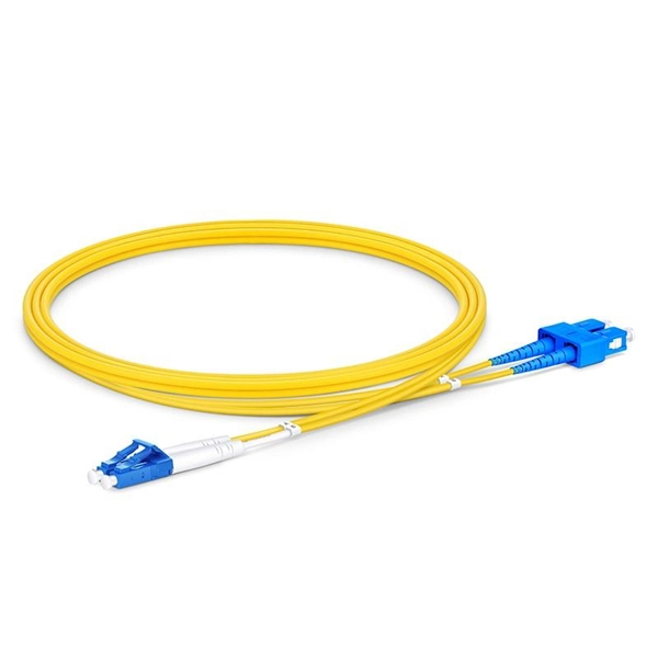
Splicing allows you to restore or expand fiber networks while maintaining signal integrity. When done right, splicing ensures minimal loss and long-lasting performance. This is where fiber optic cable splicing—the process of creating a permanent, high-performance join between two fiber ends—becomes critical. For network managers and technicians, a poor splice can lead to significant signal degradation, network downtime, and costly troubleshooting. At Turn-Key. To begin, the standard definition of splicing in optical fiber is joining two fiber optic cables together. The other, more common, method of joining fibers is called termination or connectorization. Splicing is most commonly used in the field but has application in cable assembly houses. Whether repairing a broken cable or extending a fiber run, fiber optic splicing ensures light signals travel. Whether you're installing new cables or repairing damaged ones, splicing techniques play a vital role in maintaining signal integrity. Choosing the right method affects performance, cost, and long-term durability. In this blog, we'll explore the main types of fiber optic splicing techniques, their. Joining two optical fibers at the right place so that light can be transmitted through them with minimal loss and reflection is known as splicing. Fiber optic splicing is done through two main methods. In fusion splicing, the ends of the fibers are welded together with heat. This guide will walk you.
[PDF]

Function: Analog switches are designed to pass or isolate analog signals. They essentially route analog signals based on a control signal. Examples: The CD4066B (CMOS Quad Bilateral Switch) and the SN74HC4066 (quadruple bilateral analog switch) from Texas Instruments are popular. Solid-state analog switches and multiplexers have become an essential component in the design of electronic systems which require the ability to control and select a specified transmission path for an analog signal. These switches provide bidirectional connections when “on” and high impedance paths when “off. Analog inputs are used to measure changes in process through sensors, subsequently converting that signal to voltage or current and sending it to modules that measure this change to determine new setpoints. Many remote and local I/O systems can use discrete and analog input signals. What. In the example below, an RF input signal is added to a DAC output or switched to GND. Due to the high frequency of the RF signal, any switching transients of the switch would disturb the RF output signal, thus any. Texas Instruments offers a wide variety of switches and multiplexers supporting a variety of configuration, voltage, bandwidth, and package needs. This application note summarizes the key features and performance characteristics of our analog signal switches and application considerations for.
[PDF]

A differential encoder is often used for bit synchronization. The polarity of the differentially encoded signal can be inverted without having any effect on the decoded signal waveform. A photoelectric signal, output by a photoelectric receiver, may detrimentally change after the photoelectric encoder is used for a period of time or when the environment changes; this will directly affect the accuracy of the encoder and lead to fatal errors in the encoder. To maintain its high. The grating eddy-current of DGECE consists of a circular array of trapezoidal reflection conductors and 16 trapezoidal coils with a special structure to form a differential relationship, which are respectively located on the code plate and the readout plate designed by a printed circuit board. 2 Example showing decoding is the same. This encoder signal error means your A, B, or R channels aren't correctly inverted. Learn how to test your encoder, cabling, and signal integrity. In high-performance control systems using the Siemens SINAMICS drive family, the encoder feedback is crucial. This also changes the direction of the rotation of the constellation changes. In the past I have been told channels. But I have also read that a spectral inversion is equivalent indicate this may be true.
[PDF]
Buyers typically pay a range for fiber optic cable per foot depending on fiber type, jacket, and shielding, plus installation considerations. This guide outlines typical cost ranges and the main drivers behind pricing to help formulate a budget and estimate expenses. The Fiber Broadband Association has partnered with Cartesian to research the cost of deploying fiber and provide insight on how these costs are evolving over time. In preparing this second edition of the Fiber Deployment Cost report, Cartesian gathered inputs from a wide variety of firms building. With 19+ years of experience installing fiber-optic cables at over 20,000 locations, we've seen how prices vary based on cable type, project scope, and installation complexity. This information can help project leaders engage with providers and network operators in their area. This data is based on cost information. As of August 2025, with global internet penetration reaching 67. 56 billion users worldwide, the demand for faster, more stable connections is at an all-time high. Fiber-optic technology, which transmits data via light through glass or plastic strands, offers unparalleled performance. Annual study tracks drivers to fiber broadband deployment cost WASHINGTON, D. — (January 22, 2024)—The Fiber Broadband Association today announced the results of its 2023 Fiber Deployment Cost Study, conducted by Cartesian, which provides the industry's benchmark to help fiber broadband service.
[PDF]

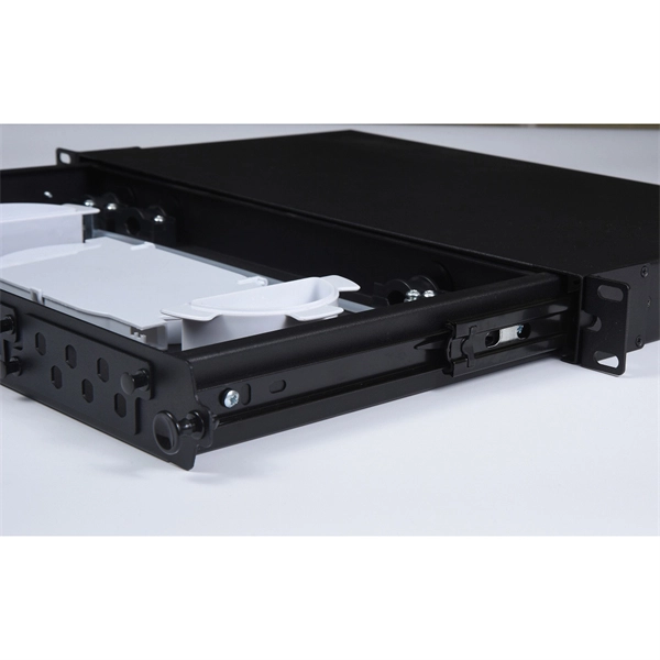
Learn how to splice 4-fiber optic cables using ODF in this complete step-by-step tutorial. Whether you are a beginner or a professional in fiber optic networking, this guide will help you splice fiber cables accurately, manage connections with ODF panels, and ensure. This complete guide explores everything you need to know about ODFs — from their structure, types, and key components, to installation best practices and modern design trends. Whether you're building a central office, data center, or FTTx distribution network, understanding the right ODF. How to Splice 4-Fiber Optic Cable with ODF | Step-by-Step Fiber Optic Splicing Tutorial. This guide demystifies ODF, exploring their design, core functions, types, and how they. An Optical Distribution Frame (ODF) is the central hub for fiber splicing, termination, patching, and cable protection in modern optical networks. It's where incoming and outgoing cables meet. It does four key things: Think of it as the central hub for your fiber network. Without it, cables get tangled. This article explores the types, components, applications, installation, and maintenance best practices, providing a.
[PDF]

The SmartAisle offering optimizes infrastructure deployment and management with an intelligent row-based system that integrates data center racks, power, row cooling, aisle containment, monitoring and control technologies for spaces with up to 40 racks. Virtiv APM UPS provides reliable, transformer-free, on-line, uninterrupted power, and KIRK key interlock system for safety. Flexible power distribution:MB Modular Busway is a flexible and more economical way to deliver power to the rack without the cost and hassle of power cable whips. Vertiv Virtual Showroom displays a range of. With multiple ways to configure for future expansion, power and cooling redundancy levels and emergency ventilation - SmartRow is a flexible solution to meet today's needs while being prepared for tomorrow's unknown. The SmartAisle infrastructure solution optimizes the deployment and management of. The Liebert Intelligent SmartAisle Containment Solution holds supply air in the cold aisle requiring the servers fans to pull the cold air through the server and into the hot aisle, thereby improving thermal efficiency. The SmartAisle infrastructure solution optimizes infrastructure deployment and.
[PDF]
