
Optical cables are born from ultra-pure glass preforms, drawn into hair-thin fibers, coated for protection, bundled strategically, and encased in durable jackets. This meticulous process ensures light-speed data transmission with minimal loss. Fiber optic cables are the backbone of today's high-speed internet, telecommunication systems, and data transfer technologies. With the increasing demand for faster and more reliable connectivity, the construction of optical fiber cable factories has become essential. In this guide, we will. The Modified Chemical Vapor Deposition (MCVD) process was developed in 1974 at Bell Labs to improve traditional Chemical Vapor Deposition (CVD) methods for fabricating optical fibers. In MCVD, a quartz tube is used as the initial substrate or source material. Fiber optic technology has revolutionized the way information is transmitted, offering numerous advantages over traditional copper wiring. What makes fiber optic cables special is their ability to. Single-mode fiber represents the pinnacle of long-distance optical transmission technology. At Sinoptec, our advanced manufacturing processes ensure each fiber meets rigorous.
[PDF]
The Open Systems Interconnection (OSI) model is a developed by the (ISO) that "provides a common basis for the coordination of standards development for the purpose of systems interconnection." In the OSI reference model, the components of a communication system are disting.
[PDF]
This article will guide you through the process of troubleshooting fiber optic connections, with a focus on ensuring proper TX and RX alignment and how to correctly switch patch cables to resolve issues. Proper connection of fiber optic cables is essential to harness these benefits fully, as even minor errors can lead to significant performance issues like signal loss. When issues like signal loss, slow speeds, or intermittent connectivity arise, systematic troubleshooting is key. This guide will walk you through diagnosing and resolving common. The process to connect fiber optic cable to router requires careful attention to detail, but I'll walk you through every critical step with the precision and clarity you deserve. This comprehensive guide combines industry standards with field-tested practices to ensure you achieve a rock-solid. Fiber optic cables are widely used in modern networks for their high-speed data transmission capabilities and resistance to electromagnetic interference. However, like any other networking technology, fiber optics can encounter issues that disrupt communication. One of the most common problems in. Fiber optic internet delivers blazing-fast speeds and reliable connectivity, making it a top choice for modern homes and businesses. Their ability to transfer large amounts of data at lightning speed makes them a go-to for efficient communication. Knowing how to avoid signal loss in.
[PDF]

In telecommunications, a base station is a fixed transceiver that is the main communication point for one or more wireless mobile client devices. It further connects the device to other. A communication base station is composed of a computer room, base station, antenna, feeder line (transmission line between transmitter and antenna), and supporting equipment. The antenna is at the top of the signal tower, and below the tower is a computer room. Along with increased capacity demands driven by the explosion of cloud and connected device growth, engineers need interconnects that enhance the design. A base transceiver station (BTS) or a baseband unit (BBU) is a piece of equipment that facilitates wireless communication between user equipment (UE) and a network. UEs are devices like mobile phones (handsets), WLL phones, computers with wireless Internet connectivity, or antennas mounted on. Fiber Optic Cables: High-speed fiber optic cables connect the BBU to the RRUs (RE part). Signal Transmission: The optical signals carry data, control, management, and synchronization information. Topology: The BBU and multiple radio heads can be connected in cascade or star configurations. The rise. The design investigates the possibilities of Free-Space Optical (FSO) communication systems and MilliMeter-Wave (MMW) technologies operating at 60. Although these technologies are highly effective and have a high throughput, they are nevertheless vulnerable to weather phenomena like rain.
[PDF]

Also, please take a look at the list of 44 communication cable manufacturers and their company rankings. Quabbin Wire & Cable Co. *Including some distributors, etc. On the Thomas Network, you'll find more than 3200 suppliers of cables in the US. You can filter these companies by location, certifications, and more factors to easily find and connect with the right supplier for your needs. We've listed the most frequently sourced cable suppliers below: Philatron. This section provides an overview for communication cables as well as their applications and principles. Dacon Systems. From Fiber Optic to Copper Cables, from the most innovative products to the smartest solutions, from industries such as Broadcast or Enterprise to Industrial or Data Center, OCC has the connections you need. We have the resources, innovative technology and industry expertise to meet the growing needs of customers around the corner and around the world. Whatever the application, our in-house engineering team of compound, process and. NAI is a global leader in the manufacturing of advanced high-reliability connectivity solutions for mission critical and other high-performance applications. Our world class integrated supply chain and operations management, combined with a global footprint in lower cost regions, provide our. Browse our broad range of connectivity products designed to help enable your communication networks. Easily create a bill of materials list.
[PDF]

Telescopic mast system with advanced vibration-dampening technology to minimize jitter and ensure stable communication and data transmission, even in the most demanding terrain and vehicle movements. Fireco designs and manufactures the most comprehensive line of standard and custom telescopic masts using high quality materials with industry leading engineering and quality testing practices to provide our customers with the world's best mobile masts. Will-Burt's telescopic masts and tower systems provide intelligent. Telescopic mast systems play a critical role in modern field operations—enabling elevation of cameras, antennas, lights, sensors, and communication gear in demanding environments. Whether for surveillance, broadcasting, defense, or emergency response, choosing the right mast system ensures reliable. Floatograph, along with its utility industry partner, Eversource Energy, developed the Rapid Pole® – Temporary Power Pole system to reduce customer downtime, allowing crews to re-energize a circuit in as little as 20 minutes. Floatograph's masts come in height options from 10 to 100 feet, and are. Advanced telescopic mast solutions designed for versatility in the field, providing crucial support for on-the-move (OTM) missions. Erecting the Telescoping Mast is made by simply connecting guys and brackets to the attached unique heavy duty rolled edge guy rings and clamps, extend the sections, insert the locking cotter pins, rotating the tubes to.
[PDF]

These invisible highways, consisting of fiber-optic wires connecting landing points, are placed hundreds of metres below the surface of the ocean by cable-laying ships. Submarine cables are laid using special cable layer ships, such as the modern René Descartes , operated by Orange Marine. A submarine communications cable is a cable laid on the seabed between land-based stations to carry telecommunication signals across stretches of ocean and sea. The first. Installing underground fiber optic cables is critical to establishing high speed internet infrastructure that delivers reliable connectivity for businesses nationwide. In this guide, we'll. Photo courtesy of ASN Red buoy markers mark the path of a submarine cable being laid in the ocean. Every day, we send countless emails, take part in video calls, use search engines and streaming services, while seamlessly banking online. These remarkable cables form the backbone of international connectivity, facilitating seamless transmission of vast amounts of information across continents.
[PDF]
If an EGC cable is installed in or on a cable tray, it should be bonded to each or alternate cable tray sections via grounding clamps (this is not required by the NEC® but it is a desirable practice). Cable tray may be used as the Equipment Grounding Conductor (EGC) in any installation where qualified persons will service the installed cable tray system. There is no restriction as to where the cable tray system is installed. The metal in cable trays may be used as the EGC as per the limitations. Cable tray grounding wire is the safety connection that links your electrical system's cable tray to the ground. This provides a safe path for any stray electrical currents to flow safely into the earth, avoiding damage to your equipment and reducing the risk of electric shocks. Grounding points and conductor locations must be determined. The design must comply with relevant regulations and standards.
[PDF]

Incoming Distribution Cable: The fiber distribution box receives an incoming distribution cable, which typically carries a bundle of optical fibers. These optical fibers originate from a central source, such as a data center, central office, or distribution point. Fiber Distribution Boxes (FDBs) are critical components in modern telecommunications infrastructure, particularly in fiber optic networks. Minimize the interference of the optical cable access signal to the external environment. The. In the complex architecture of fiber optic networks, the Optical Distribution Frame (ODF) serves as the linchpin for organizing, protecting, and distributing optical signals. Whether in data centers, telecom central offices, or enterprise network rooms, ODFs enable efficient fiber management. An optical cable consists of three primary parts: the core, the cladding, and the protective sheath. Surrounding the core is the cladding, which has a lower refractive index than the core. This complete guide explores everything you need to know about ODFs — from their structure, types, and key components, to installation best practices and modern design trends. Whether you're building a central office, data center, or FTTx distribution network, understanding the right ODF.
[PDF]

When Batelco was first founded in 1981, Bahrain already had 45,627 telephone lines in use. By 1982, the number reached 50,000. Batelco enjoyed being a monopoly in the telecommunications sector for the next two. Telecommunications in Bahrain are provided by the Bahrain Telecommunications Company, trading as Batelco, as well as other companies such as Zain and STC. Prior to 1981 telecommunications services were provided by two separate departments: national services were provided by the Bahrain. Explore the evolution of BNET in Bahrain, a testament to the nation's commitment to advancing telecommunications infrastructure and connectivity. BNET won the Gigacity Excellence Award at the WBBA Broadband Excellence Awards 2024! Learn about BNET's evolution and its journey to provide advanced. alth, and to maintaining national competitive advantage. Change in information and telecommunications technology (ICT) has accelerated over the last two ecades, and these two areas have increasingly converged. Since then, other companies such as Zain and VIVA have entered the telecommunications sector. During the same year, Optical fibres and cables were the 479th most exported product (out of 3,333) in Bahrain. In 2024, the main destinations of.
[PDF]

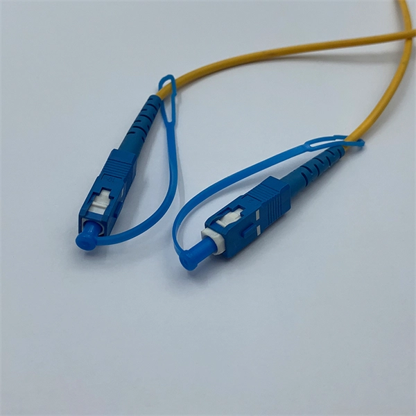
pigtails can be divided into single-mode (colored yellow) and multimode (colored orange) fiber. Multimode pigtails use 62.5/125 micron or 50/125 micron bulk multimode fiber cables and terminated them with multimode fiber optic c. pigtails can be divided into single-mode (colored yellow) and multimode (colored orange) fiber. Multimode pigtails use 62.5/125 micron or 50/125 micron bulk multimode fiber cables and terminated them with multimode fiber optic connectors at one end. 10G multimode fiber cables (OM3 or OM4) are also available in optic pigtails. The jacket color of 10. Fiber Optic Pigtails, In fiber optic cable installation, how cables are attached to the system is vital to the success of network. If done properly, optical signals would pass through the link with low attenuation and little return loss. pigtail offers an optimal way to joint optical fiber, which is used in 99% of single-mode applications. This pos. According to different types of pigtail cable connector terminated at the end, there are LC fiber pigtail, SC pigtail, ST pigtail, FC pigtail, fiber pigtail and so on. With different structures and appearance, each of them has their own advantages in different applications and systems. Let's go through some widely used ones. SC Pigtail: SC pigtail.
[PDF]

Without proper crimping, even minor movements can cause the cable's fibers to shift, resulting in a weak or broken connection. it also facilitates a smooth and efficient signal. When manufacturing fiber optic cable assemblies, a relatively simple step can have dire consequences if not done accurately. This is true for crimping. In fact, once all. To attach the connector to the fiber, the installer can use glue or crimping. An epoxy or other adhesive can be used to glue the fiber into the connector's ferrule, and the end of the fiber then polished. The epoxy needs curing, which can take overnight, or be speeded up using a curing oven. An. We terminate fiber optic cable two ways - with connectors that can mate two fibers to create a temporary joint and/or connect the fiber to a piece of network gear or with splices which create a permanent joint between the two fibers. A poor crimp will lead to mechanical distress resulting in optical performance d perator's training and manufacturing engineering support. The purpose of this document is to provide guidance on SENKO's recommended nted for electrical. At the heart of any robust fiber optic network lies a crucial process: Preparing a fiber cable for termination of a connector or splice. Two types of splices are used in fiber optic cabling one is Mechanical the other is Fusion. Whether you're installing a new network, expanding an existing one, or.
[PDF]
This article is about the Internet Outages Map, which provides a visualization of global internet health over the last 24 hours. It also includes information on how to use this map and what data it collects, as well.
[PDF]


