Because fiber optic cables don't come in one continuous length, sections must be joined together through splicing. This process fuses two glass strands so light signals can travel through them without interruption. Below is a detailed look at each step of fiber optic network construction, including key terms and methods used across the industry. Engineers and. We are experts in the installation and use of fiber optic cable to residences, apartment buildings, businesses and cell sites. We complete complex construction projects consisting of aerial and underground deployments in varied, often difficult, working environments. Our services include everything. The Fiber Optic Association, Inc. (FOA) was founded in 1995 to help develop the workforce to build the fiber optic networks to support a rapid expansion in communications and the Internet. Delivers state-of-the-art fiber optics solutions by developing high-tech equipment and subcontractor expertise. Utilizes state-of-the-art technologies to splice a wide variety of different. This recommended practices document is a comprehensive manual for optical fiber construction and testing. Sections are included for project management; cable handling, testing and equipment; overhead cable placement; underground cable placement; underground enclosures; bonding and grounding; cable. 4. FO-VC2 JOINT USE - VERICAL MIDSPAN CLEARANCES 48. FO-GB GROUNDING AND BONDING 49.
[PDF]

This guide covers everything: what fiber optic pigtails are, how they differ from patch cords, which connector and polish type to specify, how to choose between mechanical and fusion splicing, and the real-world applications where pigtails are the right call. In this guide, we cover the basics of fiber optic splicing, how to perform splicing using two different methods, and finally some best practices to perform good fiber splicing. What is Fiber Optic Splicing and Why is it Needed? – #1. Whether you're building out an ODF. Think of a fiber optic cable splice as the seamless stitching that keeps data flowing through the delicate threads of a network—like a master tailor joining fabric with precision. Whether repairing a broken cable or extending a fiber run, fiber optic splicing ensures light signals travel. Fibre optic splicing is an essential skill in the world of modern telecommunications, offering a reliable method to connect optical fibres for seamless data transmission. As the demand for high-speed internet and robust communication networks continues to grow, learning to splice fibre optics is. In this guide, you will find a chronological description of the fusion splicing process, the principal technical standards, and answers to the real-life questions network engineers and procurement teams may have. Therefore, we will also touch on cost factors, risk management, and best practices in.
[PDF]
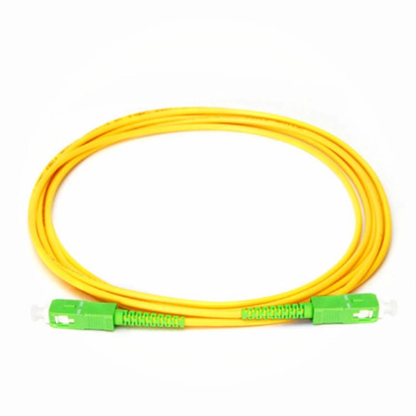
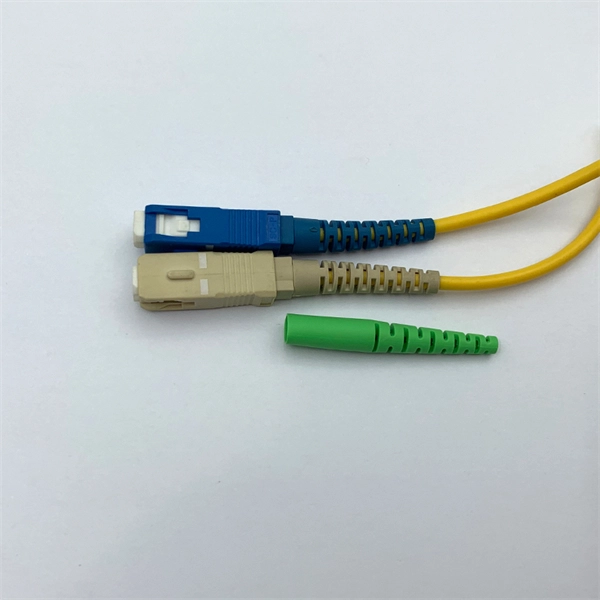
When the heat-shrinkable tube is tightened after splicing, the residual pollutants (such as tiny sand particles) will press the optical fiber and cause the optical fiber to deform, so the splicing loss will increase. At this time, the fiber needs to be cleaned. A fiber optic pigtail is a fiber optic cable with one end terminated with a factory-installed connector and the other end unterminated. As a result, the connector side can be connected to equipment, while the other side is fused in the case of fusion splicing and a mechanical connection in the case. Executive Summary: A fiber optic pigtail is one of the most commonly specified yet least understood components in structured cabling. The guide provides the complete workflow, covering safety precautions, tool selection, fiber preparation, fusion operation, quality control, and. Removes the protective coating to expose the bare fiber for splicing, ensuring no scratches or nicks. Produces a clean, precise fiber end face, critical for low-loss fusion or mechanical splicing. Precisely aligns and fuses fiber ends to form a stable, low-loss connection suitable for long-term. The scientific fiber coiling method can make the optical fiber layout reasonable, the additional loss is small, can withstand the test of time and harsh environment, and can avoid the phenomenon of fiber breakage caused by extrusion. Optic Fiber Management Rules 1. Coil the fibers along the.
[PDF]

Learn how to install fiber splice trays inside an enclosure step by step. Quick, easy, and essential for fiber pigtail management! https://bit. Unlike fiber connectors, which can be plugged and unplugged, splicing creates a fixed connection that is typically more stable and has lower insertion. This document describes the installation of optical fiber with both single fiber and/or ribbon fiber splices into Optical Splice Enclosure (OSE) metal splice trays (Figure 1). Make sure you read and understand this instruction as well as instructions provided with related assemblies before. By following these detailed steps, the installation of your Fiber Splice Closure will be secure, organized, and maintained, ensuring high performance and longevity of your fiber optic network. Installing a fiber optic splice closure efficiently and effectively requires attention to detail and. How to install the splitter distribution box is the important information we need to know. This article includes the following: 1. Install the fixture 2. Box installation and fixed splitter distribution box 4. Install. Page 5 B (# 7 & 8) enter splice tray # 2. Route the fibers entering the splice tray up to splice point as shown. NOTE : Protection tube from side A enters splice tray from the far end as shown After splicing, close the splice tray and lock the front cover properly with the main and side lock.
[PDF]

The two primary industry-accepted methods for fiber optic cable splicing are fusion splicing and mechanical splicing. The choice between them depends on performance requirements, budget constraints, and the specific application environment. To begin, the standard definition of splicing in optical fiber is joining two fiber optic cables together. Splicing is most commonly used in the field but has application in cable assembly houses. Infield. In this guide, we cover the basics of fiber optic splicing, how to perform splicing using two different methods, and finally some best practices to perform good fiber splicing. What is Fiber Optic Splicing and Why is it Needed? – #1. In this guide, we'll explore what splicing of fiber entails, why it's important, and dive into the key methods and tools. So in essence, fiber optic splicing is a process used to join two separate fiber optic cables together. Through splicing, fiber optic technicians can extend the length of the fiber to make it long enough for use in a required cable run. As. Splicing fiber optic cable is an extremely important phase for making dependable, high-speed communication infrastructures. Termination is the other, more frequent way of linking fibers. Fiber splicing is the preferred way when cable lines are too long for a single length of fiber or when combining two different types of cable.
[PDF]

Main cost drivers include on-site labor, specialized fusion splicing, testing, and any necessary restoration of network performance. This guide provides practical cost ranges in USD with clear low–average–high estimates to help budgeting and planning. Fiber optic splicing costs vary widely depending on project size, location, fiber type, and site conditions. For most commercial projects, expect to pay $50–$150 per fusion splice point — but that number can swing in either direction based on the factors below. The "per splice" rate is the most. There are two primary methods of splicing fiber optic cables: fusion splicing and mechanical splicing. Each method has distinct characteristics and costs associated with it. Fusion Splicing: This method involves aligning two fiber ends and using an electric arc to melt them together, creating a. Adtell Integration is capable of supporting your fusion splicing requirements whether they require Singlemode, Multimode, or Ribbon Splicing. Fusion Splicing Services: Contractor/Customer Fusion Splicing & Installation Services: Adtell integration offers nationwide fusion splicing services. Specifically fiber used for internet. -W2 employee for a decent size telecommunication contractor, all.
[PDF]

In this guide, you will find a chronological description of the fusion splicing process, the principal technical standards, and answers to the real-life questions network engineers and procurement teams may have. 📦 For purchasing, use the RP Photonics Buyer's Guide for fusion splicers. It provides an expert-curated supplier directory, buyer-focused technical background information, and structured selection criteria to support professional procurement decisions. This article explains the principle of fusion. Fusion splicers play a crucial role in the field of optical fibre communications by enabling the permanent bonding of two strands of glass fibre to create a continuous pathway for light to travel through. This process is achieved through precise alignment and fusion of the fibre ends using an. Fusion splicing is the process of fusing or welding two fibers together usually by an electric arc. Fusion splicing is the most widely used method of splicing as it provides for the lowest loss and least reflectance, as well as providing the strongest and most reliable joint between two fibers. Each splicer is equipped with a cleaver and stripper, conveniently includes in a single case. The goal is to align the microscopic glass cores (typically.
[PDF]
Yes. Standard scissors and a ruler will be adequate in most cases, unless you require an exact length of tubing, in which case use a more precise measuring tool. For thicker tubing you may require wire cutt.
[PDF]

A fiber is used to support G. 691 with a maximum rate of STM-16 or 10Gbit/s and a maximum transmission distance of 40 km (Ethernet) and STM-256 for G. This document outlines the specifications for a single-mode optical fiber and cable designed for use around the 1310 nm zero-dispersion wavelength, suitable for both the 1310 nm and 1550 nm regions, and compatible with analogue and digital transmission. It details the fiber's geometrical, optical. G. 652 is an international standard that describes the geometrical, mechanical, and transmission attributes of a single-mode optical fibre and cable, developed by the Standardization Sector of the International Telecommunication Union (ITU-T) that specifies the most popular type of single-mode. G. 652 optical fiber is a kind of optical fiber that is widely used in the network. 652 is mainly based on the requirements of PMD and the attenuation requirements at 1383nm. 652D is the type of optical fiber in the optical cable, which represents non-dispersion-shifted single-mode fiber, and is currently the most widely used single-mode fiber in China. This article will provide a detailed introduction to the structure, characteristics, and applications of standard single-mode fiber. G652 is a specification for optical fiber cables. It is part of the International Telecommunication Union (ITU-T) G.
[PDF]

BiDi SFP+ changes the geometry: each module uses a single fiber pair directionally separated by wavelength, so you can run one strand where you previously needed two. One of the most common decisions network engineers face is selecting between single fiber SFP and dual fiber SFP modules. This comprehensive guide explores the differences between single and dual fiber SFPs, their respective benefits, limitations, and use cases—helping you make an informed choice. A single fiber SFP, also known as a BiDi SFP, is designed precisely for this purpose—enabling bidirectional data transmission over a single strand of optical fiber. Unlike traditional SFP transceivers that require two fibers—one for transmitting and one for receiving—a single fiber SFP uses. SFP (Small Form-factor Pluggable) is a compact, hot-pluggable network interface module used to connect network devices (switches, routers, firewalls) to fiber optic or copper cables. An SFP interface on networking hardware is a modular slot for a media-specific transceiver, such as for a fiber-optic cable or a copper. Both transmitting and receiving need one optical fiber to connect. Simplex SFP modules, also known as BIDI transceiver, employs a unidirectional transmission mechanism and have only one port. In practice, that means fewer splice points, smaller patch panels, and less conduit congestion—especially in retrofit buildings.
[PDF]
Fiber testing is the process of verifying the performance of optical fiber cabling. This process includes a range of tests and measurements such as insertion loss, optical return loss, and fiber length. It encompass.
[PDF]
In a fused fiber splitter, the input fiber is aligned with the fused region, which causes the optical power to be divided between the output fibers. The tapering process gradually guides the light from the input fiber to the output fibers, resulting in a proportional split of the. A fiber-optic splitter, also known as a beam splitter, is based on a quartz substrate of an integrated waveguide optical power distribution device, similar to a coaxial cable transmission system. The optical network system uses an optical signal coupled to the branch distribution. It plays a crucial role in enabling multiple devices to share a single fiber optic connection, maximizing the utilization of the available. Essentially, a fiber optic splitter performs the following actions: Light Enters: Light travelling through a fiber optic cable enters the splitter. Passive Separation: Inside the splitter, the light is split into multiple separate beams using optical components. Conversely, it can also combine multiple signals into one. Its primary role is in Passive Optical Networks (PON), which are the foundation of. A fiber optic splitter is a passive optical component that divides a single incoming optical signal into two or more outgoing signals, or combines multiple incoming signals into one. However, modern splitters can have multiple inputs and outputs, allowing for the distribution of a single signal to dozens of receivers. The internal workings of a passive.
[PDF]

A distribution box, also known as a fiber distribution hub or optical distribution box, is a larger enclosure designed to manage and distribute fiber optic cables to multiple endpoints. It serves as a central point for connecting and organizing numerous fiber optic. Although all three are related to fiber connection and management, their installation locations, functional roles, and positions within the network architecture are fundamentally different. Confusing these devices may lead to non-standard cabling at best, and serious challenges in network. In modern FTTH (Fiber to the Home) and optical communication networks, three types of fiber distribution products are widely used: Splitter Distribution Box, ODF (Optical Distribution Frame), and Fiber Terminal Box. The functions of the four connectors can be. First, let us learn the common point among ODF, fibre optic termination box and fiber optical distribution box, actually, they have similar function, we sort out them as following 4 aspects: 1. fiber termination and optical signal splitting 4. What is the difference between these fiber boxes.
[PDF]