Cable trays are mechanical support systems that provide a rigid structural system for electrical cables, raceways, and insulated conductors used for electric power distribution, control, signal instrumentation, and communication. Cable trays are used as an alternative to open wiring or electrical conduit systems, and are commonly used for cable management in. maintain spacing or to keep cables in place when the tray is ect the minimum bend ra-dius for cables as they exit the bottom of the cable tray. Metal cable trays are made of galvanized steel, stainless steel, and. The modern world relies heavily on electrical and communication cables that must be managed and supported across vast distances in commercial and industrial settings. A cable tray is an organized support structure designed to secure and route these insulated electrical cables. It acts as a. For safe application, observe the following: WARNING To prevent from shock, short-circuits or damage, observe the following: • Be sure the power is disconnected before replacement (fuse exchange, etc. • Use this product in a properly maintained condition. (Replace or repair if the body. What is a cable tray? A cable tray is a metal or non-metal structure used to lay electrical cables and wires, serving to support, protect, and guide the cables. What is the role of a cable tray in electrical engineering? A cable tray allows for the neat and aesthetic arrangement of cables.
[PDF]

CT-S3T-2 tower section weight does not exceed 26 kg. Transmission tower weight per meter varies dramatically by voltage level: 35kV towers average 100-180 kg/m, 66kV systems run 150-250 kg/m, 110kV towers range 200-450 kg/m, 220kV structures reach 350-600 kg/m, and 500kV ultra-high voltage towers require 500-800 kg/m. This weight increases. Due to the complicated nature of tower infrastructure, it can prove invaluable to have an engineer approved recommendation for solutions that will accommodate your particular project. We offer a Tower Recommendation Proposal Consultation Service, providing a detailed report that you can use for the. 18m Telecom Tower Ma /www. inf. ASMTower automatically performs load calculation on telecom structures, wind load, ice load and dead load according to the following design standards: ASMTower performs wind and ice load calculations according to the chosen code and distributes the resulting loads, along with the weight of the. Get Latest Price from the seller Khan Enterprises - Offering Selp Sport Wi-Fi Tower, Size: 18 Mtr Rtt at ₹ 3500/meter in Bengaluru, Karnataka. Get WiFi Tower at lowest price | ID: 20500615430. Now, let's take a look at the pricing options: 1. Non-upgradeable: • 12 meters: R49,990. 00 ex VAT ex works PLUS R49,000. 00 ex VAT for site visit, civils, and installation.
[PDF]
6Wresearch actively monitors the Nauru Telecom Towers and Allied Services Market and publishes its comprehensive annual report, highlighting emerging trends, growth drivers, revenue analysis, and forecast outlook. Welcome to Nauru Fibre Cable Corporation (NFCC), your gateway to reliable, high-speed internet and telecommunication services. Our insights help. The Department of ICT is governed by the Communications and Broadcasting Act 2018. The Department focuses on providing a reliable and resilient telecommunications infrastructure for all government departments and offices, schools and health clinics. Established in 2019, the company focuses on the design, construction, and management of telecom towers. Tawal operates a substantial portfolio of over 16,000 towers across the Kingdom, making it the first TowerCo.
[PDF]

In the drawing that is not at 1:1 scale, find an object or line whose length you know. Start the scaling command with SC (or SCALE). Make a selection for the objects that need to be included in the scaling operation. Click in the drawing for the first point of the. AutoCAD 2D drawings are commonly drawn in model space at a 1:1 scale (full-size). In other words, a 12-foot wall is drawn at that size. The drawings are then plotted or printed at a plot "scale" that accurately resizes the model objects to fit on paper at a given scale such as 1/8" = 1'. In some. To scale a CAD drawing object that has been inserted into another application, you typically access its properties to adjust the display size relative to the page or other elements. Scaling a CAD drawing, particularly when it's embedded or linked in another document like a technical diagram or. In this video, I'll show you how to scale any object to an exact size in AutoCAD—perfect for resizing blocks, drawings, or imported items to match real-world dimensions. This process ensures that all elements in your designs are proportionally accurate, allowing for efficient layouts and designs. Selecting the Object. The below table shows you how to set the scale within paper space in AutoCAD to the correct scales. Scaling refers to the proportionate resizing of an object within a drawing. In 2D CAD, it ensures that objects fit within the drawing space while maintaining real-world proportions.
[PDF]

This free DWG file includes a well-organized collection of switches, sockets, DB symbols, lighting points, junction boxes, and earthing details. Along with that, it provides installation guidelines such as conduit fixing, wiring connections, and mounting heights. Download free collection of AutoCAD details for electrical systems. All installation details for electrical design of building including the various systems in electrical field such as power distribution, lighting, earthing, electrical cables, distribution boards and many other electrical system. Development of an electrical installation that contains detail from well to ground; box with symbols; electrical outlet installation detail; distribution board and technical specifications. If you are working on Electrical Shop Drawings or preparing as-built layouts, having a complete set of standard AutoCAD electrical symbols and installation details can save you hours of drafting time. Detailed cutaway of the lighting box. Our collection features high-quality resources from top manufacturers, available in both 2D and 3D formats to support your electrical projects. This. Free CAD and BIM blocks library - content for AutoCAD, AutoCAD LT, Revit, Inventor, Fusion 360 and other 2D and 3D CAD applications by Autodesk. CAD blocks and files can be downloaded in the formats DWG, RFA, IPT, F3D. You can exchange useful blocks and symbols with other CAD and BIM users.
[PDF]
The hot and cold aisles in the data center are part of an energy-efficient layout for server racksand other computing equipment. The goal of a hot/cold aisle configuration is to manage airflow in a way that c.
[PDF]

Use the MTEXT command in AutoCAD to create and edit multiline text with formatting, columns, styles, and fields. Learn when to use MTEXT instead of TEXT. I'm wanting to create documentation for a control fiber optic network. Can anyone help me out? Some examples of a diagram would also help. 10-27-2018 01:41 AM Do you know if there's some symbol standard. Search by part number or description such as CAT5, CAT6, OSP, etc. Sort by any of the table headers. Use the drop down menu to filter by product category and type. Sort by any. Be among the first to receive important product updates, insights and news. Discover all CAD files of the "Optic fiber connectors" category from Supplier-Certified Catalogs ✅ SOLIDWORKS, Inventor, Creo, CATIA, Solid Edge, autoCAD, Revit and many more CAD software but also as STEP, STL, IGES, STL, DWG, DXF and more neutral CAD formats. Free CAD and BIM blocks library - content for AutoCAD, AutoCAD LT, Revit, Inventor, Fusion 360 and other 2D and 3D CAD applications by Autodesk. CAD blocks and files can be downloaded in the formats DWG, RFA, IPT, F3D. You can exchange useful blocks and symbols with other CAD and BIM users. The two linetypes are shown below. The appearance is similar but slightly different. Does anyone have such a code that they could share with me? I struggled for an hour or so and came up with this. There is a small gap on the left side of the circle.
[PDF]

We are offering a comprehensive, fabrication-ready CAD file for a standard electrical distribution box. This isn't just a simple layout; it's a detailed mechanical drawing intended for electrical engineers, panel builders, and fabricators. High-performing, reliable product solutions that transmit data, power and signal in cars, planes, power grids, appliances, electro. Discover all CAD files of the "Power Distribution Boxes" category from Supplier-Certified Catalogs ✅ SOLIDWORKS, Inventor, Creo, CATIA, Solid Edge, autoCAD, Revit. The CAD files and renderings posted to this website are created, uploaded and managed by third-party community members. This content and associated text is in no way sponsored by or affiliated with any company, organization, or real-world good that it may purport to portray. It is running model of. Development of a distribution box for a meter. Download CAD block in DWG. 22 KB). Disassembly of a distribution box of a Perkins engine Already Subscribed? Free download Distribution box in DWG format or CAD block. This component, also known as a breaker panel or consumer unit, is the central nervous system for power management in any residential, commercial, or industrial setting. We design and manufacture a range of electrical products for the distribution, protection, control and management of electrical systems in low voltage environments. We help our customers to design and build their own.
[PDF]

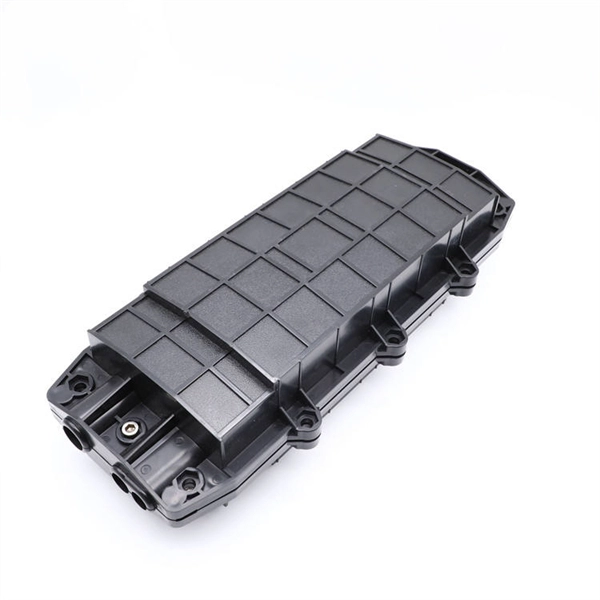
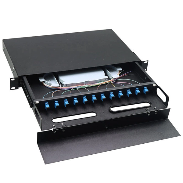
Optical Network Terminals (ONTs): Often called "fiber boxes," ONTs are located inside homes and connect the fiber optic cable to the internal network. They receive the optical signal from the external fiber optic cable and convert it into a usable signal for home networking equipment. A fiber optic junction box, also known as a fiber optic distribution box or termination box, is a protective enclosure that facilitates the connection and management of fiber optic cables. It serves as a central point for organizing and distributing optical fibers, ensuring efficient connectivity. A Fiber Terminal Box (FTB) is a customer-side termination and distribution device used at the end of the optical network. Key Functions Typical Applications ZION FTB Highlights In essence: The Fiber Terminal Box is an end-user termination device for small-scale distribution. ■ What Is a Fiber. Fiber junction boxes play a crucial role in the organization, protection, and distribution of fiber optic cables in various applications, including telecommunications, data centers, and industrial networks. Primary Purpose: Its core function is to provide a secure, protected location. To handle a large number of optical fibers with lower cost and higher flexibility, various optical junction boxes are widely used to connect and arrange optical fibers. The distribution box provides.
[PDF]

At Least Three to Six Feet Away: A commonly suggested distance for minimizing RF exposure is three to six feet (approximately 1-2 meters) from your bed. If possible, aim for six feet or more, especially if you are sensitive to electromagnetic fields (EMFs). The safe distance from a WiFi router depends on the router's power and the level of exposure you are comfortable with. Here are some general guidelines: Minimum Distance: Experts recommend maintaining at least 10 feet (3 meters) from a WiFi router to reduce radiation exposure significantly. Ideal. Keep the router away from high-traffic areas like bedrooms, nurseries, or places where you spend long periods. We typically recommend at least 10 feet away from where you spend most of your time. Instead, place it in a location where it can still emit sufficient coverage but minimize unnecessary. While there are no strict guidelines, most experts recommend keeping a reasonable distance between your WiFi router and sleeping area. Some studies have pointed to a higher risk of sleep disturbance, decreased cognitive function, and even potentially cancer with prolonged proximity to WiFi radiation. Dual-band routers emit signals on 2. At these distances, RF exposure drops to low or minimal levels while maintaining reliable connectivity. For maximum protection during sleep, position your router.
[PDF]
There are several factors that can impact the cost of a dedicated internet line. Some of them are out of a customer's control, but some are not. Understanding these factors can help businesses make informe.
[PDF]