The in-service monitoring of civil infrastructures is an important task required to achieve their smart operation. This task requires the installation of sensors to continuously check and control the structures' st.
[PDF]
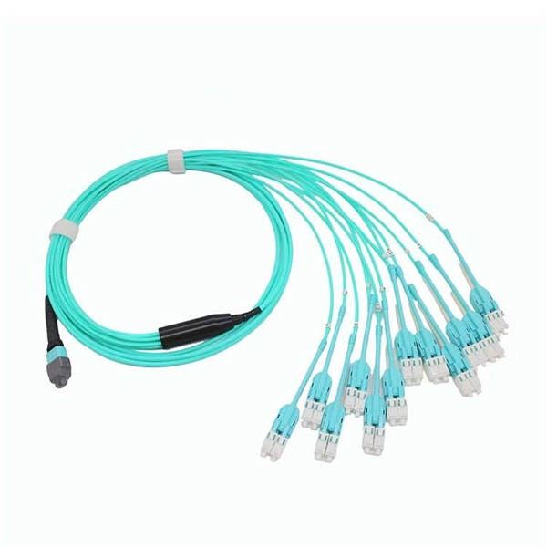
In practice, there are two main ways to terminate fiber optic cable: using a connector to join two fibers to create a temporary, removable joint, or using splicing technology to permanently join two bare fibers directly. Either. Terminating fiber optic cables essentially means putting connectors on fiber optic cable so that you can connect the cable to various devices or network components. Think of it as the equivalent of connecting the dots in a complex puzzle; without proper termination, the whole system can break down. Fiber optic networks are the backbone of modern communication systems, enabling high-speed data transfer and reliable connectivity. When deploying fiber optic cabling, one of the most critical decisions is how to terminate the fiber—either by splicing or using connectors. The process of fiber optic cable termination is the essential act of connecting fiber optic cables to devices, patch panels, or other cables to enable. This Applications Engineering Note explains how different optical fiber termination methods impact the optical performance of telecommunications systems. Optical fiber cabling systems support various communications technologies that use digital as well as analog signaling. This involves either installing a connector or creating a splice to establish a reliable connection point for the optical signal.
[PDF]
G657A2 bending insensitive singlemode fiber combines two attractive features: excellent low macro-bending sensitivity and low water-peak level. It is comprehensively optimized for use in O-E-S-C-L band (1260 -1625 nm). FOSC ® 450 B6 Fiber Optic Splice Closure, Gel Cable sealing, no pre-installed tray, 6 cable attach., three ground feedthrough lugs, with test valve, Build America Buy America (BABA) Finish making your selections or clear them to view relevant specifications. B2 Including the IEC 60793-2-50 type Bl. b2 Optical Fiber Specification. Use the code in the “Fiber Type” column to replace the XX notation in the catalog number shown on the catalog page. This identifies the fiber that will be provided with the cable choice. The fibers in all completed cables are tested 100% at the factory for attenuation, and each fiber must meet the. trip force (Force to mechanically strip the and ≤ 5. low water-peak level. It is comprehensively optimized for use in O-E-S-C-L band. Outdoor dry core optical fiber Multi Loose Tube cable with glass yarns as strength member, Corrugated Steel Tape (Full Rodent Protected) armor and polyethylene outer jacket. Product feature: This cable has improved rodent protection by Corrugated Steel Tape (Full Rodent Protected). Existing out of.
[PDF]
A multi-mode optical core can transmit multiple channels of data at the same time, while single-mode can only transmit one channel of data at the same time. Therefore, the quality and distance of single-mod.
[PDF]

In this article, we will walk you through the process of pulling fiber optic cable through conduit. We will cover everything from understanding the components involved to troubleshooting common issues that may arise during the installation process. Fiber optic cable is surprisingly strong, durable and pliable; however, several best practices should be followed to ensure a successful cable installation. Most fiber damage does not come from normal operation after the system is live. It happens during installation, when excessive pulling force, tight bends. This helps keep fiber optic cables safe from harm and signal problems when you put them in. Use the right lubricant. Follow the rules for tension and bend radius. This makes sure the cable pull is smooth and safe. Try new methods like air blowing. Use smart monitoring devices. In most cities, that is how the majority of cable is installed. A duct is available from point A to point B, a pull tape is blown in, a fiber optic cable is attached to it. When deploying fiber links in data centers, LANs, or even in outside plant networks, fiber is pulled between equipment and spaces through pathways, cable managers, cable tray, risers, or conduit. While it may seem like a routine task, failure to pull properly can damage the cable in a way that.
[PDF]

This guide presents ranges in USD and practical price estimates to help budget planning. Indoor OM3/OM4 vs outdoor armoured increases price. Cost varies by grade and vendor. Includes trenching, conduit, termination. Connector type affects cost. Local rules vary widely. Distance. Buyers typically pay for fiber optic cable by length, fiber type, and installation complexity. Commercial building installations with 100-200 network drops generally range from $15,000 to $30,000. This guide presents cost ranges in. Let's be real: If you are wondering “how much does fiber optic cable cost” for your next project, you've probably seen quotes that make zero sense. One supplier in your inbox promises $0. 05 a foot, while a domestic distributor is asking for ten times that. You search “how much does fiber optic. Typically, per drop fiber cabling prices range from $250 – $1000 per drop depending on the type of fiber (OM2, OM3, OM4, or OM5), multi or single mode, PVC or plenum, average drop length, and also the number of fibers in each cable. Adding switches, high-end enclosures and other issues can also. Pricing (USD) Filter the results in the table by unit price based on your quantity. A tariff of 8% may be applied if shipping to the United States.
[PDF]

Get price quotes for Fiber Bragg Grating. Contact suppliers directly with one click. Use this fiber Bragg gratings buying guide to compare major types, define selection criteria, and find suppliers: Professional purchasing of high-value photonics products is a substantial responsibility, where a structured decision-making process is essential. RP Photonics offers a lot of help: Get. Comparing fiber bragg grating sensor prices. How does 6W market outlook report help businesses in making decisions? 6W monitors the market across 60+ countries Globally, publishing an annual market outlook report that analyses trends, key drivers, Size, Volume, Revenue, opportunities, and market segments. All our Fiber Bragg Grating Arrays and Cable models are designed to make handling and deployment fast, easy and intuitive. Technica. Transmission spectrum for a sample FBG with center wavelength of 1546. 83nm and 90% reflectivity: Please note: the FBG is made on bare single mode fiber and has no steel tube or any other types of package. © 2024 CB Cabling Technologies Ltd.
[PDF]

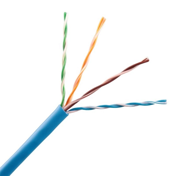
This article provides a detailed technical comparison between fiber optic and copper cables, offering a clear perspective for engineers, network architects, and procurement managers. The core distinction between the two technologies lies in the physics of data. However, the exponential growth in data demand has positioned fiber optic technology as the superior alternative for performance, scalability, and future-readiness., 10G/25G/40G/100G and beyond depending on optics and reach). Copper Ethernet scales too, but practical limits are lower and depend. The two main options are fiber optic cables and copper cables, each with its own advantages and drawbacks. Fiber optic cables are praised for their high performance and scalability, while copper cables remain a cost-effective choice, especially for budget-conscious projects and older systems. Copper wire is more susceptible to interference and has limited data capacity, making optical fiber the preferred choice for modern high-speed. Optical connectivity, utilizing fiber-optic technology, has emerged as the superior choice for modern networking, offering unparalleled performance, reliability, and scalability. For example, a typical 10 Gbps copper Ethernet link (such as Cat 6A) over 100 meters can consume approximately 5 to 8+.
[PDF]
Genuine Modules mentions that the cost of fiber optics per kilometer can range from $10,000 to $50,000, depending on various factors such as the type of fiber, installation method, terrain, and region. Fiber-optic cable materials typically cost $1 to $6 per linear foot, depending on fiber count and cable type. Commercial building installations with 100-200 network drops generally range from $15,000 to $30,000. Single-mode fiber costs less per foot than multimode fiber, but it requires more. The price of fiber optic cabling depends on cable type, length, installation method, and surrounding materials. Typical costs hinge on fiber count, indoor versus outdoor use, and whether trenching, splicing, or termination is required. This guide provides practical ranges in USD and practical price. Discover 6 core fiber optic cable 1km price with GYXTW armored outdoor design, G652D fiber, CE/ROHS, ideal for 5G FTTH networks. Knowing how much fiber optic cable costs, which factors can impact cost, and key cost considerations can help you avoid unnecessary expense and get the most out of your budget. 50 per meter, depending on several variables. Here's a general pricing reference: These are indicative prices based on standard configurations. Custom-built cables or niche specifications can lead to higher prices. 30Single-mode Outdoor Cable$0. 50Multimode (OM1/OM2/OM3)$0.
[PDF]

When Batelco was first founded in 1981, Bahrain already had 45,627 telephone lines in use. By 1982, the number reached 50,000. Batelco enjoyed being a monopoly in the telecommunications sector for the next two. Telecommunications in Bahrain are provided by the Bahrain Telecommunications Company, trading as Batelco, as well as other companies such as Zain and STC. Prior to 1981 telecommunications services were provided by two separate departments: national services were provided by the Bahrain. Explore the evolution of BNET in Bahrain, a testament to the nation's commitment to advancing telecommunications infrastructure and connectivity. BNET won the Gigacity Excellence Award at the WBBA Broadband Excellence Awards 2024! Learn about BNET's evolution and its journey to provide advanced. alth, and to maintaining national competitive advantage. Change in information and telecommunications technology (ICT) has accelerated over the last two ecades, and these two areas have increasingly converged. Since then, other companies such as Zain and VIVA have entered the telecommunications sector. During the same year, Optical fibres and cables were the 479th most exported product (out of 3,333) in Bahrain. In 2024, the main destinations of.
[PDF]

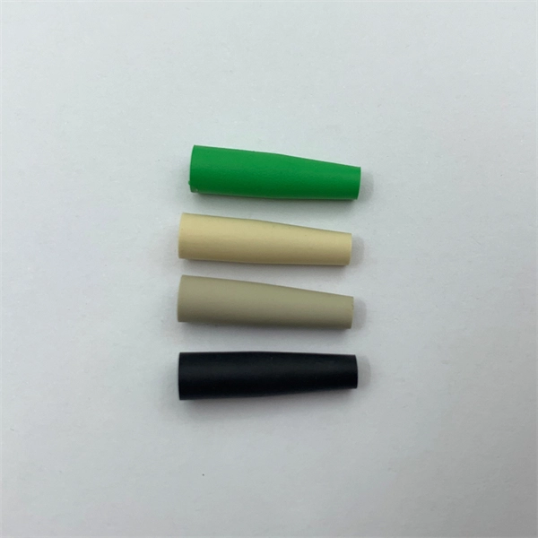
IEC fiber connector standards establish the global specifications for connector geometry, mating interfaces, optical performance classes, and mechanical testing across all fiber network environments. Optical connectors are used to connect optical devices to other optical devices or systems. However, each connection introduces a certain amount of insertion and return loss that. Connectors play an important role in Enterprise network architecture. They give you the power to add, drop, move, and change the network. is a small cylinder used to mount. The Fischer FiberOptic Series offers robust and faultless optical performances in any conditions. Combined with easy use, cleaning and maintenance. Tested for harsh and extreme environments (Norm IEC 61753-1 Cat. These standards ensure that passive fiber-optic components remain interoperable, stable, and. designed for diverse fiber optic applications. But what exactly sets a fibe optic connector apart in terms of its merits? The primary purpose of a fiber optic connector is to terminate the ends of fiber optic cables, ensuring they can be int rconnected reliably with minimal optical loss. After. Fiber optic technology is used in ever-increasing applications due to its inherent advantages (lower weight, EMI/RFI immunity, higher bandwidths and distances) over copper. There are many.
[PDF]

Learn how to splice fiber optic cable using fusion splicing with this complete step-by-step guide. Includes tools, best practices, loss standards (ITU-T G. 652), cost analysis, and FAQs for network engineers and installers. Splicing fiber optic cable is an extremely important phase for making dependable, high-speed communication infrastructures. Regardless of the type of fiber network you're deploying, be it for telecom, enterprise data centers, or smart city infrastructure, fusion splicing provides the benefits of. This is where fiber optic cable splicing—the process of creating a permanent, high-performance join between two fiber ends—becomes critical. For network managers and technicians, a poor splice can lead to significant signal degradation, network downtime, and costly troubleshooting. At Turn-Key. Think of a fiber optic cable splice as the seamless stitching that keeps data flowing through the delicate threads of a network—like a master tailor joining fabric with precision. What is Fiber Optic Splicing and Why is it Needed? – #1. Discover how to efficiently use sleeves and the heat. The answer lies in splicing, both fusion and mechanical. In this comprehensive guide, we will delve into when.
[PDF]

For example, in a FTTH network, a single fiber from the telecom provider can serve 32 homes using a 1:32 splitter, eliminating the need for separate fibers to each residence. These unassuming devices enable a single optical signal to be divided into multiple paths, making them indispensable for sharing network resources efficiently—from residential FTTH (Fiber-to-the-Home) connections to large-scale telecom backbones. This guide demystifies fiber optic splitters. You use optical couplers and splitters to split or join signals in fiber networks. These devices help you control light signals well. For example, optical splitters send light to many output ports. It can divide the input optical signal into multiple output optical signals to meet the fiber optic access needs of multiple terminal devices. This type of device plays an important role in passive. A fiber-optic splitter, also known as a beam splitter, is based on a quartz substrate of an integrated waveguide optical power distribution device, similar to a coaxial cable transmission system. The optical network system uses an optical signal coupled to the branch distribution. The fiber optic. If you've ever wondered how a single fiber from your internet service provider can deliver service to an entire neighborhood or apartment building, you've wondered about the magic of optical splitters. The process of light beam splitting involves.
[PDF]

