In this article, you will learn the step-by-step process of testing your solar panels using a multimeter. We will cover the essential tools you need, the specific measurements to take, and how to interpret the results. A $15 multimeter and 5 minutes of testing can diagnose most solar panel problems. Measure Voc (open circuit voltage) — if it reads 0V, the panel or wiring is dead. If it reads 60–80 % of rated, a bypass diode has failed. By the end of this guide, you will be equipped with the knowledge to diagnose. Learning how to test solar panel with multimeter is useful for homeowners, technicians, farmers, and anyone using solar energy systems. A digital multimeter allows you to check voltage, current, continuity, and resistance. Fluke recommends using the Fluke 117 Electrician's Multimeter or Fluke 283 FC CAT III 1500 V Digital Multimeter to test solar modules. Here's how a technician tests solar modules with a multimeter:. A multimeter is an indispensable tool for anyone working with solar panels, allowing for accurate measurements and diagnostics. It empowers users to assess the performance, identify faults, and ensure optimal energy production. Perfect for DIY solar builders, RV owners, o. more Audio tracks for some languages.
[PDF]

Testing solar panels is easy with a multimeter! To test the current, simply connect the multimeter to the panel's output. Set it to read DC current. To test voltage, set your multimeter to. A $15 multimeter and 5 minutes of testing can diagnose most solar panel problems. Measure Voc (open circuit voltage) — if it reads 0V, the panel or wiring is dead. If it reads 60–80 % of rated, a bypass diode has failed. If Voc is normal but the system is not producing, the problem is downstream. Solar panels are usually tested under standard conditions using a light source that mimics the light from the sun on a clear day. You can use the following method if you want to test your solar panel under standard conditions. We will cover the. A multimeter is a tool that measures the voltage, current, and resistance of an electrical circuit. Fluke recommends using the Fluke 117 Electrician's Multimeter or Fluke 283 FC CAT III 1500 V Digital Multimeter to test solar modules. This helps you spot issues early and keep your system running efficiently. By the end of this guide, you will be equipped with the knowledge to diagnose.
[PDF]
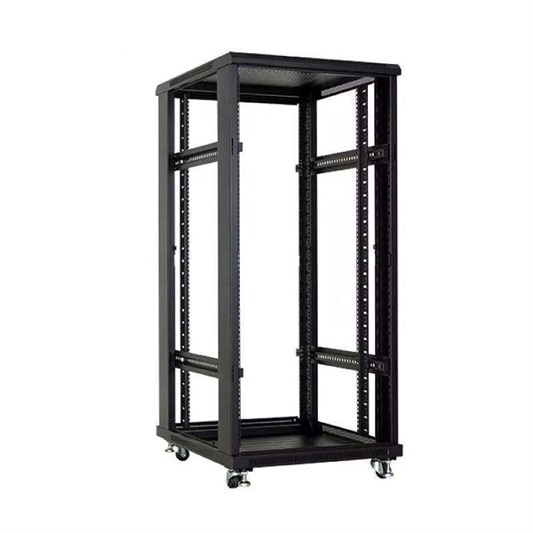
A 24-port patch panel is a networking device that allows for the organization and management of incoming and outgoing network connections. It acts as an interface between different devices such as computers, switches, and routers, allowing for easy connectivity and communication. This guide explains how to use a 24-port patch panel to manage copper and fiber cabling in a small LAN, how to choose between different patch panel types, how to design your cabinet layout, and why a patch panel is still irreplaceable in 2026. What is a Patch Panel and Why it Matters in 2026? A. Choosing a 24-port patch panel is crucial for efficiency. Learn how it enhances network capabilities. Typically, patch panels are available in a huge number of port densities from 12. In this article, we will define what a patch panel 24 port is, explain its purpose, and discuss why it is a crucial component in organising network cables. A patch panel 24 port is a device used in network cabling to connect and organise multiple network cables in one central location. It is a. Choose a 24-port patch panel when you care about clean labeling, comfortable “finger room,” and fast moves/adds/changes—especially if technicians touch the rack often and you want straightforward port-to-port mapping (Panel 01–24 ↔ Switch 01–24). Choose based on port density, cabinet space.
[PDF]
Dual door fiber enclosures provide our highest level of distribution panel security. They give you the option to separately lock the network and distribution doors for more control over panel access. The second doo.
[PDF]
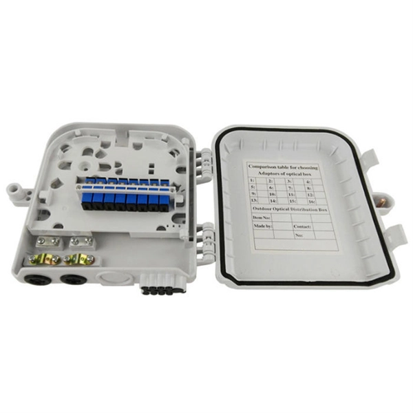
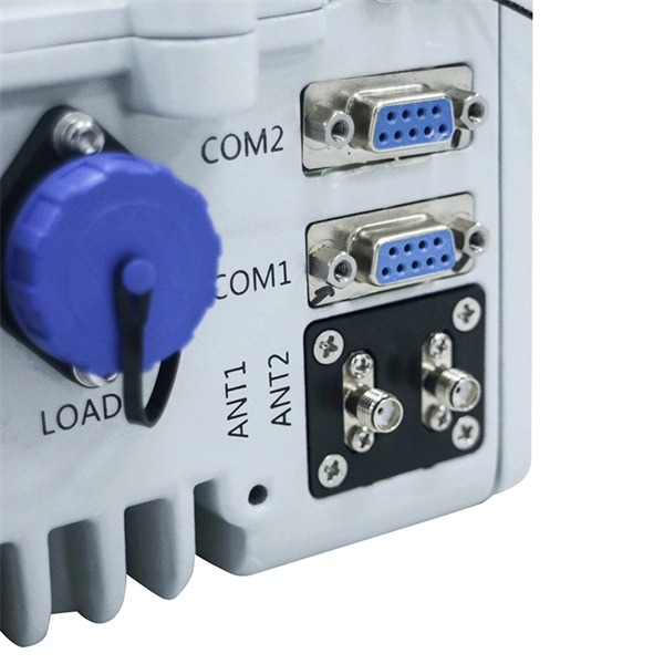
Designed to provide a clean, secure, and accessible termination point for indoor fiber connections, these outlets ensure optimal signal quality and minimal interference in residential and commercial environments. As fiber-to-the-home (FTTH) and fiber broadband continue to replace traditional copper infrastructure, the Fiber Optic Socket Wall Outlet has become an essential component of modern optical networks. These outlets act as the key connection point between your fiber optic cables and the devices that require fast, stable internet. A fiber wall socket (also called an optical termination outlet or FTTH outlet) is the critical endpoint where your home's fiber optic cable connects to the Optical Network Terminal (ONT). It ensures a clean, stable interface between the ISP's fiber network and your router—impacting speed, latency. These outlets, also known as fiber wall sockets or fiber optic outlets, play a crucial role in facilitating the transmission of data over long distances at incredible speeds. Splice holder is included. The optical trunk outlet is designed for installation in Schneider/Thorsman 80mm ducts. Trunk outlet for fiber optics delivered with adapter and pigtails.
[PDF]

A typical fiber connector (the plug-and-socket type you'd find on patch panels) adds around 0. 5 dB of loss per connection. Higher-quality connectors under ideal conditions can get down to about 0. Attenuation in fiber optics is the gradual loss of light signal strength as it travels through a fiber cable. It's measured in decibels per kilometer (dB/km), and it determines how far a signal can travel before it becomes too weak to read. A standard single-mode fiber operating at 1550 nm loses. Optical Signal Attenuation is the single greatest factor limiting the distance and performance of your network. Understanding it is crucial for anyone involved in data centers, telecommunications, or enterprise networking. This guide will demystify signal loss, explore its causes, and show you how. F iber optic networks rely on the efficient transmission of light signals to deliver high-speed data over long distances. However, various factors can cause signal degradation, leading to performance issues and reduced network reliability. Fiber optic signal loss, also known as attenuation, occurs. Home1 / Blog2 / fiber optic3 / How to Fix High Attenuation & Signal Loss in Fiber Optic Networks. Signal loss in Fiber Optic networks can make data slow. High attenuation makes your system not work well. You may see slower speeds and less steady connections when signal loss goes up. Things like impurities in the fiber core and reflections at the core-cladding edge cause this drop.
[PDF]
The Patch and Splice Combo Patch Panel is designed to allow both the patching and splicing of fiber optic cable all in one unit; these particular units have fiber termination panels in the upper slide out shelf and splice trays in the lower shelf. NG4access ® Cabled Modules available in all module sizes and fiber counts up to 864 fibers NG4access ® Splice Tray Four sizes of interchangeable Propel fiber pass-through adapter packs provide the breadth of capabilities for virtually any configuration. Four sizes of interchangeable Propel fiber. Cisco is introducing a family of fiber management solutions with a debut of SMF and MMF patch panels. The panels will enable Cisco's customers to facilitate breakout connectivity agnostic of the data rate. The Cisco® solution of panel and cable assemblies offers versatile solution for any breakout. Our fiber patch panel offers options for flexible cable management and seamless integration with various cassettes and fiber optic accessories. Allowing full front access for network. Foss FP-series front patch panels are made with the highest accuracy for precise fitting. All panels are tested according to both our own quality measures and international standards before they are sent to customers. Similarly, the ABS High Density Shelves bring a new level of access, convenience, and security to its Fiber Splice Shelf, enabling quick and easy fiber splicing and connectivity for rack mount applications.
[PDF]
The applicable subheading for the fiber optic panel/chassis and fiber optic patch tray, will be 9403. 8040, Harmonized Tariff Schedule of the United States (HTSUS), which provides for “Other furniture and parts thereof: Parts: Other: Other; Of metal. ” The rate of duty will be free. Item 1, part number LCXE-M1RU-BLK, is described as a fiber optic chassis with the capabilities of holding twelve fiber optic cables. The panel is produced from cold rolled. The merchandise is fiber optic patch panels that provide a consolidated point of demarcation for optical terminations, connections and cross connections within a passive, fiber optic network. They are designed to be mounted onto a wall or rack. All fiber optic patch panels will consist of the. Find verified buyers and sellers of Fiber Optic Patch Panel in 180+ countries along with their valid phone numbers and email ids. The top 3 Buyer countries for HS Code 851770 are “ PHILIPPINES ”, “ INDIA ”, “ PAKISTAN ”,. com if you have any questions or special project needs. The panel is produced from cold rolled. In the United States, customs duties imposed on imports from Asian countries have increased costs for Internet service providers and telecommunications companies, in many cases delaying infrastructure expansion and maintenance projects. In Latin America, several countries have adopted tariff.
[PDF]

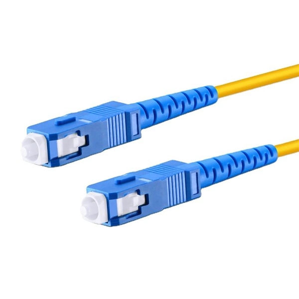
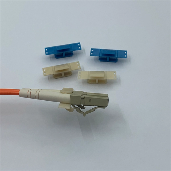
In this video, Joe would display how to connect SC fiber optical connector in 2 minutes. Related product:. Step 4 i s to affix the fiber to the connector. The fiber should be inserted into the connector until it is flush with the ferrule end. Step 5: Let the epoxy cure. These connectors ensure high-quality signal transmission, which is essential for reliable internet and communication services. SC APC connectors offer superior optical. There are many types of fiber optic connectors, including SC, LC, FC, ST, D4, MU, MT/MPO, etc. These connectors can be divided into single-mode and multi-mode fiber optic connectors according to their structure and purpose. To learn more about the types of fiber optic connectors, click here: Types. The global SC fiber optic connector market is valued at approximately 903 million USD in 2025 and is projected to grow steadily, which reflects its continuing role as a standard interface in fiber infrastructure, including plant backbones and industrial automation links, according to SC connector. SC fiber connectors, or Subscriber Connectors, are widely used in telecom and networking for their strong performance and easy handling. They're known for a secure push-pull connection that's quick to insert and remove.
[PDF]

A fiber patch panel is a mounted enclosure—either rack-mounted or wall-mounted—used to terminate, manage, and interconnect multiple fiber optic cables. It acts as a hub for organizing splices and patch cords, streamlining fiber management and preserving signal integrity. Propel Series Sliding Fiber Optic Panels for holding Propel modules, adapter packs and splice cassettes EPX Fiber Optic Panel available in either G2 or LGX/PNL 1U, 2U or 4U fixed or sliding configurations FMT (Fiber Management Tray) Series Fiber Optic Panels FOMS-FPS and FOMS-FPS-HD Fiber. Consolidate your fiber optic connections in industrial environments with our DIN rail patch panel, with a modular design and tool-free installation save space and simplify deployment. Consolidate your fiber optic connections in industrial environments with our DIN rail patch panel, with a modular. Belden offers several Fiber Patching Systems. Cable Organization:. FS offers FHD® FAPs and FHU™ 1U fiber patch panel with LC, SC, MTP®/MPO connectors in singlemode/multimode fiber to deploy medium for high-density fiber optic network applications. Foss FP-series front patch panels are made with the highest accuracy for precise fitting. All panels are tested according to both our own quality measures and international standards before they are sent to customers. In an FTTH network hub—whether a central office, local exchange, or data.
[PDF]

Cable tray/protective casings are to be assigned with a safe Working Load. The test should be performed according to IEC 60068-2-75:2014 pendulum hammer. (Refer the sketch shown below) The test should be carried out on samples of cable tray lengths or cable ladder. Cable tray load testing ensures your trays can hold the weight without bending or breaking. The bearing capacity is the most basic testing item for the quality of the cable tray. The load-bearing test is also called the SWL (safe working load) test, which is to test the bearing capacity of the cable tray according to the standards of the International Electrotechnical Association. The. Meka Pro measures the safe workload of the cable management systems and corresponding deflection in accordance with the IEC 61537 standard. The safe workload (SWL) is a load [kg/m] that creates a deflection of 1/100 in the span, or if a 1/100 deflection is not achieved, it is the force that creates. This international standard outlines the requirements and tests for cable tray systems used for electrical installations. Whether you're a manufacturer, contractor, or quality assurance engineer, understanding the testing behind IEC 61537 can help ensure your systems meet global safety benchmarks. Samples of ladder should consist of two side-members with one rung positioned centrally. Sa es of the plastics can be maintained for the intended purpose and the installation location. In this particular.
[PDF]

One of the most common ways to test fiber optic cables is with a light source, which emits light through the cable to detect any potential problems. LED light sources emit. Fiber optic cables are a top choice for high-speed communication systems and can also serve as sensors to measure and monitor various quantities. Modern. Document the end-to-end results for the fiber optic segment you just tested. Related: Data Center Cabling Best Practice Guide Using optical time domain reflectometer testing, you'll measure the length of the fiber optic cable, attenuation, and any events occurring on that fiber segment. Events are. A photodiode is a semiconductor diode sensitive to photon radiation, such as visible light, infrared or ultraviolet radiation, X-rays and gamma rays. It produces an electrical current when it absorbs photons. This can be used for detection and measurement applications, or for the generation of. A typical fiber optic communication system consists of three primary components: a transmitter, a fiber optic cable (the transmission medium), and a receiver. The transmitter usually incorporates a Light Emitting Diode (LED) which converts digital binary data into light waves. The studies cover fiber optic components that have standard SMA connectors to couple with SMA-SMA connectorised PMMA (plas otodiode and a phototransistor. It has a built-in optical power meter an the associated power supplies. Apart from LPS04, the accessories.
[PDF]

In Q1 2019 NSS Labs performed an independent test of the Oracle Talari SD-WAN E1000 v7. NSS has created three use cases to represent the most common reasons why enterprises deploy software-defined wide area network (SD-WAN) products: Manageability & Cost, Performance, and Security. The troubleshooting tools are now easily accessible from the various monitoring pages of Cisco SD-WAN Manager, such as Site Topology, Devices, Tunnels, and Applications, thereby providing you with context-based troubleshooting guidance. For information on interface bandwidth, see the Interface Summary Report. This report is available in WatchGuard Cloud for Fireboxes that run Fireware v12. To view the report, you must configure. The Monitoring tab is a dashboard that displays a summary widgets of all your SD-WAN device health metrics. This tool provides actionable intelligence about the activity on your SD-WAN network, by allowing you to quickly identify applications or links experiencing performance issues. The ideal. Certifications, manuals, datasheets, and specifications for hundreds of thousands of electronic devices. Jump directly to brand. be attenuated by at least 30 dB relative to the maximum in-band peak PSD level in 100 kHz. Set the RBW = 100 kHz, VBW = 300 kHz, Detector = peak. Set Sweep time = auto couple, Trace mode = max hold. Use the peak marker function to determine the maximum amplitude level.
[PDF]