In Q1 2019 NSS Labs performed an independent test of the Oracle Talari SD-WAN E1000 v7. NSS has created three use cases to represent the most common reasons why enterprises deploy software-defined wide area network (SD-WAN) products: Manageability & Cost, Performance, and Security. The troubleshooting tools are now easily accessible from the various monitoring pages of Cisco SD-WAN Manager, such as Site Topology, Devices, Tunnels, and Applications, thereby providing you with context-based troubleshooting guidance. For information on interface bandwidth, see the Interface Summary Report. This report is available in WatchGuard Cloud for Fireboxes that run Fireware v12. To view the report, you must configure. The Monitoring tab is a dashboard that displays a summary widgets of all your SD-WAN device health metrics. This tool provides actionable intelligence about the activity on your SD-WAN network, by allowing you to quickly identify applications or links experiencing performance issues. The ideal. Certifications, manuals, datasheets, and specifications for hundreds of thousands of electronic devices. Jump directly to brand. be attenuated by at least 30 dB relative to the maximum in-band peak PSD level in 100 kHz. Set the RBW = 100 kHz, VBW = 300 kHz, Detector = peak. Set Sweep time = auto couple, Trace mode = max hold. Use the peak marker function to determine the maximum amplitude level.
[PDF]
Its function is to split two incident light beams from two individual input fiber cables into sixty-four light beams and transmit them through sixty-four individual output fiber cables. A fiber-optic splitter, also known as a beam splitter, is based on a quartz substrate of an integrated waveguide optical power distribution device, similar to a coaxial cable transmission system. The optical network system uses an optical signal coupled to the branch distribution. These devices are commonly used in fiber optic networks to distribute signals to various endpoints. Optical splitters work by using a branching mechanism that allows the signal to be evenly. An optical splitter is a crucial passive fiber optic device that splits and combines optical signals. It can distribute the optical energy transmitted through a single fiber to two or more fibers in a predetermined ratio or combine the optical energy from multiple fibers into one fiber. Optical splitter.
[PDF]
Dual ring topology is a network configuration that uses two concurrent rings of connections to link devices. This redundant network structure enhances reliability and provides a failover mechanism, ensuring high availability and network uptime. Device Level Ring (DLR) is a Layer 2 protocol that enables redundancy in a ring topology, providing fast network fault detection and reconfiguration for industrial networks. DLR is an EtherNet/IP™ protocol that is defined by the Open DeviceNet® Vendors' Association (ODVA). DLR network includes at. A fiber optic ring network is a physical or logical network topology where devices (usually switches) are connected in a closed-loop using fiber optic cables. Each node is connected to two other nodes, forming a ring-like structure. This design ensures data can travel in both directions. Data travels from node to node, with each node along the way handling every packet. Rings can be unidirectional, with all traffic. This document provides basic background information regarding adding ring redundancy in your wired Ethernet networks. It will explore the N-Tron proprietary protocol N-Ring and how it is a step up from IEEE Spanning Tree and Rapid Spanning Tree Protocol (STP, RSTP). DLR provides a means to detect, manage, and recover from single faults in a ring-based network. A DLR network includes the following types of ring nodes.
[PDF]

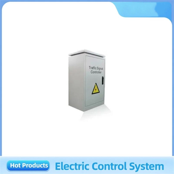
Mount individual circuit breakers in the designated positions within the distribution box. Each breaker should match the current rating and type required for its specific circuit. Ensure proper connection to the busbars and secure mounting to prevent loosening over time. Correct wiring methods for circuit breakers within distribution boxes are fundamental to ensuring electrical safety and compliance with established codes. The distinction between 1P and 2P circuit breakers plays a pivotal role in determining the appropriate protection level for various circuits. This guide shows you how to organize circuit breaker wiring properly. You will learn to build a safe, efficient, and professional electrical system today. Circuit breaker wiring configurations involve organizing main switches, busbars. Circuit breakers, as important components in distribution boxes, can protect circuits from the effect of overload and short circuits. It serves as a central hub for distributing electricity throughout a building, ensuring that power is delivered safely and efficiently to all the required locations. We'll also look at whether it's good enough for your home, and what to do if your panel needs an upgrade. We want to help keep your home powered safely and. A breaker box, also known as a circuit breaker panel, is an essential component of any electrical system. To understand how a breaker box works, it is helpful to.
[PDF]

A distribution boxes acts as the load center and main distributor of electrical power within a building. Also called a distribution board, panel board, breaker panel, or electric panel, it is the central hub in an electrical system that divides incoming power into various subsidiary. 💡 Quick Answer: An outdoor electrical junction box is a weatherproof enclosure where electrical wires connect or split, required by code to protect connections from moisture, provide safe access for maintenance, and prevent electrical hazards in exterior applications. It takes the incoming power and safely distributes it to different circuits throughout your building. Whether in a home or an industrial facility, this box keeps your electrical setup organized, functional, and efficient. However, the key to. NEC Article 314 establishes requirements for the installation and use of electrical boxes, conduit bodies, fittings, and handhole enclosures. A conduit body is a removable-cover section of a conduit system that provides access at junctions or termination points. It receives power from the main electrical supply and divides it into separate circuits, each. An electrical sub panel, also known as a sub distribution board or sub circuit breaker panel, is a smaller secondary panel connected to the main electrical panel in a building.
[PDF]

The answer is no; fiber internet doesn't need a traditional modem. A standard cable or DSL modem's job is to convert electrical signals into digital data that your devices can understand. But since fiber transmits data as light instead of electricity, there's no need for that type of. When it comes to land-based high-speed broadband connections, there are currently two competing technologies: Coaxial Cable vs. Fiber-optic, or Cable vs. This post will briefly explain the two and offer tips for handling their broadband terminal devices: the Cable modem vs. the. Fiber optic is an internet connection that uses fiber optic cables to transmit data at rapid speeds by using light pulses instead of traditional copper wire and electricity. Fiber optic can be used to establish higher bandwidth internet connections for homes and businesses compared to alternatives. Fiber internet transmits data using light signals through fiber-optic cables, which differs from traditional DSL or cable internet. Instead of a modem, fiber connections require an Optical Network Terminal (ONT), a device that converts fiber signals into an Ethernet connection. The short answer is no. These devices serve a similar purpose but function differently. However, what they do have in common is converting digital data from the computer into the format of the transmission system—for example, converting electrical impulses into the light pulses used.
[PDF]

It's called a breaker box, and even though it might not look very exciting on the outside, what's behind that little door is the heart of your home's electrical system. Bottom Line Up Front: Your home's distribution box (electrical panel) is typically located in the basement, garage, utility room, or mounted outside near your electrical meter. To find it quickly, look for a rectangular gray metal box about the size of a medicine cabinet, often positioned close to. Electrical panel boxes, aka breaker boxes, can be on a wall in an out-of-the-way area of your home. You can find electric panels inside cabinets, behind refrigerators, or inside clothes closets in older homes. Current National Electrical Codes (NEC) allow none of these locations. Electrical panels. The electrical panel is the central hub that distributes electricity throughout the house. Knowing where to find your electrical panel in your home helps in case of emergencies and routine maintenance. Panels are commonly found in garages, basements, utility rooms, and outdoor walls. Understanding how your electrical panel works can help you troubleshoot issues, perform basic maintenance, and know when to. When something electrical goes wrong in your home—like a tripped circuit or sudden power outage in one part of the house—most people instinctively head to that gray metal panel, often hidden in a basement, utility closet, or garage. Having the breaker box.
[PDF]
Choose an SFP module based on the fiber optic cabling that will be connected to the network switches. In addition, fiber cables can transmit data over several kilometers without signal degradation, making them ideal for connecting switches in large campus networks and between different buildings. As they do not emit electromagnetic signals, they're difficult to tap and secure against eavesdropping. Most modern SFP transceiver modules. Hi Experts, I have a basic knowledge of network and need some help. I need to connect 4 Floor Building with 4 Cisco 2960 - 48 ports switch each other and it needs to be through a fiber. So all PCs connected to each switch would reach the LAN/WAN from the other switch. (attached is the image here. Fiber optic cabling is increasingly used to connect network switches and other datacom equipment, especially in long-distance and mission-critical applications. Fiber provides: Increased internet signal bandwidth. Another way is to put a switch at Location B and interconnect using SFP modules. But is it possible to connect AB and BC cables using fiber optic patch cords ? Will it work in this fashion ? If this can work, I. We can use either the cat6 cable or fiber optical cable to link two network switch. One of the advantages of fiber optical cable is its fast speed. In this video, you will see how to link two network ports together to achieve 2G bandwidth between the switches. You even can connect more.
[PDF]
Can two switches with fiber ports be directly connected through fiber ports? The answer is yes. The connection between two or more Ethernet switches in a certain way (Uplink port, etc. ) is. Switch optical port intercommunication means that the optical fiber ports of two switches are connected to each other to achieve the purpose of network connection. Fiber optic technology is widely used in networking due to its high-speed data transmission capabilities and long-distance coverage. SFP transceiver modules almost always require two fiber optic cable strands. Fiber provides: Increased internet signal bandwidth. ) is called the cascade. Traditionally, network switches have been connected using copper cables, but with the increasing demand for high-speed and reliable connectivity, fiber optic cables have gained prominence. This article aims to provide a comprehensive understanding of how network switches are connected to fiber.
[PDF]

These are connected to the main panel through a circuit. A distribution box is the heart of any electrical system. It takes the incoming power and safely distributes it to different circuits throughout your building. Whether in a home or an industrial facility, this box keeps your electrical setup organized, functional, and efficient. Today, electrical systems are essential for homes and industries. But what exactly is a power distribution box, and why is it so essential in our daily lives? The DB panel board controls the flow of electricity. A typical electrical distribution. A well-chosen and properly installed distribution box can prevent electrical hazards, reduce downtime, and ensure your electrical system operates smoothly for years to come. Let's explore how these critical components work and why they deserve your attention. A distribution box, also known as a. Welcome to our channel! In this video, we'll walk you through the process of wiring a home distribution box with a detailed connection diagram. more Welcome to our. A distribution board (also known as panelboard, circuit breaker panel, breaker panel, circuit breaker, electric panel, fuse box or DB box) is a component of an electricity supply system that divides an electrical power feed into subsidiary circuits while providing a protective fuse or circuit.
[PDF]

Testing solar panels is easy with a multimeter! To test the current, simply connect the multimeter to the panel's output. Set it to read DC current. To test voltage, set your multimeter to. A $15 multimeter and 5 minutes of testing can diagnose most solar panel problems. Measure Voc (open circuit voltage) — if it reads 0V, the panel or wiring is dead. If it reads 60–80 % of rated, a bypass diode has failed. If Voc is normal but the system is not producing, the problem is downstream. Solar panels are usually tested under standard conditions using a light source that mimics the light from the sun on a clear day. You can use the following method if you want to test your solar panel under standard conditions. We will cover the. A multimeter is a tool that measures the voltage, current, and resistance of an electrical circuit. Fluke recommends using the Fluke 117 Electrician's Multimeter or Fluke 283 FC CAT III 1500 V Digital Multimeter to test solar modules. This helps you spot issues early and keep your system running efficiently. By the end of this guide, you will be equipped with the knowledge to diagnose.
[PDF]

When it comes to testing fiber optic cables, a Visual Fault Locator (VFL) is an essential tool in your toolkit. A VFL is used to detect faults, breaks, or bends in fiber optic cables by emitting a bright red light that is visible even through the fiber's jacket. Let's dive into everything you need to know about mastering VFLs. It's a cost-effective and. Visual Fault Locator (VFL) testing is one of the most fundamental inspection methods used in FTTH, ODN, and data center environments. A VFL emits a visible red laser (typically 650 nm) that travels along the fiber core and leaks out at points of excessive loss, fiber breaks, or microbends. Although. The Fiber Visual Fault Locator Kit is an essential tool for network technicians and engineers; it provides an accurate and quick method of finding such problems as breaks, bends or faults that may affect the network's operation. It works by injecting a visible red laser light (usually in the 650nm wavelength) into the fiber. When the light encounters a fault, such as a break, bend, or bad splice, it leaks out of the fiber, making the. Conducting efficient, repeatable fiber optic cable certification requires an array of specialized test equipment: Optical Loss Test Set (OLTS) – Integrates adjustable light source and power meter for efficient, Tier-1 insertion loss testing. Visual Fault Locators – Handheld devices projecting.
[PDF]

In a news conference today at the University of Chicago, the U. Department of Energy unveiled a report that lays out a blueprint strategy for the development of a national quantum internet, bringing the United States to the forefront of the global quantum race and ushering in a. In a news conference today at the University of Chicago, the U. Exploration and reserves, storage, imports and exports, production, prices, sales. Sales, revenue and prices, power plants, fuel use, stocks, generation, trade, demand & emissions. In the next 20 years, almost three billion people will join the middle class, propelling global demand for more and better housing, televisions, cars, food, water, energy, and myriad other goods and services. But, with increasing strain on the planet's resources, meeting this demand could carry. Husain is director of the FREEDM Systems Center With funding from the National Science Foundation (NSF) leveraged by additional industry support, the Engineering Research Center has sparked the growth of dozens of clean energy businesses in Raleigh's Research Triangle, making the region an. In a news conference today at the University of Chicago, the U. Below are quick statistical highlights providing an overview of the industry. For more detailed information, please see EEI's other resources. 2024 National Energy Resource Mix Coal.
[PDF]