Multiplexing: A multiplexer (MUX) combines wavelengths using thin-film filters or arrayed waveguide gratings (AWGs), ensuring <0. In fiber-optic communications, wavelength-division multiplexing (WDM) is a technology which multiplexes a number of optical carrier signals onto a single optical fiber by using different wavelengths (i., colors) of laser light. This technique enables bidirectional communications over a. This tutorial covers the fundamentals of DWDM (Dense Wavelength Division Multiplexing), including the DWDM transmitter and receiver. We'll also delve into optical fiber basics, optical amplifiers (EDFA), and other essential system components. DWDM is essentially an optical multiplexing technique. This allows multiple channels of data to be transmitted simultaneously. Wavelength Division Multiplexing (WDM) is a technology that enables multiple optical signals to be transmitted over a single fiber optic cable, significantly increasing the overall bandwidth and capacity of the network.
[PDF]
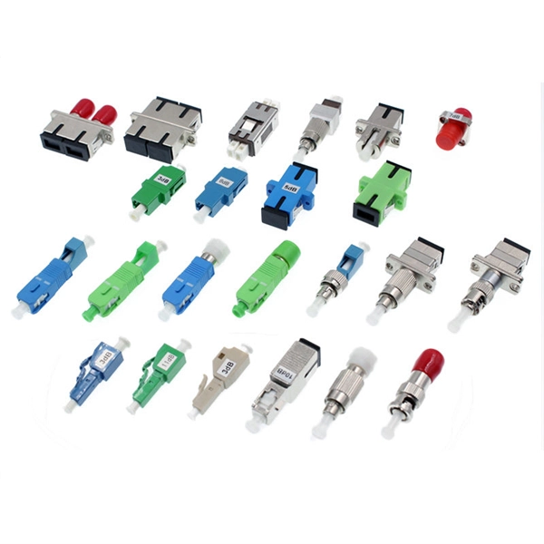
Transceivers Since communication over a single wavelength is one-way (simplex communication), and most practical communication systems require two-way (duplex communication) communication, two wavelengths will be required if on the same fiber; if separate fibers are used in a so-called fiber pair, then the same wavelength is normally used and it is not WDM. As a result, at each end both a transmitter and a receiver will be required. A combination of a transmitter and a receiver is called a transceiver; it conv.
[PDF]
WDM systems are divided into three different wavelength patterns: normal (WDM), coarse (CWDM) and dense (DWDM). Normal WDM (sometimes called BWDM) uses the two normal wavelengths 1310 and 1550 nm on one fiber. Coarse WDM provides up to 16 channels across multiple transmission windows of silica fibers. OverviewIn, wavelength-division multiplexing (WDM) is a technology which a number of signals onto a single by using different (i.e., colors) of. A WDM system uses a at the to join the several signals together and a at the to split them apart. With the right type of fiber, it is possible to have a device that does both s.
[PDF]

Cable tray/protective casings are to be assigned with a safe Working Load. The test should be performed according to IEC 60068-2-75:2014 pendulum hammer. (Refer the sketch shown below) The test should be carried out on samples of cable tray lengths or cable ladder. Cable tray load testing ensures your trays can hold the weight without bending or breaking. The bearing capacity is the most basic testing item for the quality of the cable tray. The load-bearing test is also called the SWL (safe working load) test, which is to test the bearing capacity of the cable tray according to the standards of the International Electrotechnical Association. The. Meka Pro measures the safe workload of the cable management systems and corresponding deflection in accordance with the IEC 61537 standard. The safe workload (SWL) is a load [kg/m] that creates a deflection of 1/100 in the span, or if a 1/100 deflection is not achieved, it is the force that creates. This international standard outlines the requirements and tests for cable tray systems used for electrical installations. Whether you're a manufacturer, contractor, or quality assurance engineer, understanding the testing behind IEC 61537 can help ensure your systems meet global safety benchmarks. Samples of ladder should consist of two side-members with one rung positioned centrally. Sa es of the plastics can be maintained for the intended purpose and the installation location. In this particular.
[PDF]
An OTDR is a powerful tool that helps technicians and engineers assess the health of fiber optic cables. OTDRs inject high-powered light pulses into the fiber using specialized laser diodes. As these light pul.
[PDF]
A WDM system uses a at the to join the several signals together and a at the to split them apart. With the right type of fiber, it is possible to have a device that does both simultaneously and can function as an. The optical filtering devices used have conventionally been (stable solid-state single-frequency in the form of.
[PDF]
It essentially performs some relatively simple time-division multiplexing of lower-rate signals into a higher-rate carrier within the system (a common example is the ability to accept 4 OC-48s and then output a single OC-192 in the 1,550 nm band).OverviewIn, wavelength-division multiplexing (WDM) is a technology which a number of signals onto a single by using different (i.e., colors) of. A WDM system uses a at the to join the several signals together and a at the to split them apart. With the right type of fiber, it is possible to have a device that does both s.
[PDF]
Normal WDM (sometimes called BWDM) uses the two normal wavelengths 1310 and 1550 nm on one fiber. Coarse WDM provides up to 16 channels across multiple transmission windows of silica fibers. Dense WDM (DWDM) uses the C-Band (1530 nm-1565 nm) transmission window but with denser channel spacing.OverviewIn, wavelength-division multiplexing (WDM) is a technology which a number of signals onto a single by using different (i.e., colors) of. A WDM system uses a at the to join the several signals together and a at the to split them apart. With the right type of fiber, it is possible to have a device that does both s.
[PDF]

Normal WDM (sometimes called BWDM) uses the two normal wavelengths 1310 and 1550 nm on one fiber. Coarse WDM provides up to 16 channels across multiple transmission windows of silica fibers. Dense WDM (DWDM) uses the C-Band (1530 nm-1565 nm) transmission window but with denser. In fiber-optic communications, wavelength-division multiplexing (WDM) is a technology which multiplexes a number of optical carrier signals onto a single optical fiber by using different wavelengths (i., colors) of laser light. This technique enables bidirectional communications over a. This section contains examples of wavelength division multiplexing (WDM) circuits. Wavelength division multiplexing is a method of modulating multiple signals at different wavelengths (channels) to transmit them on a single waveguide or fiber. This guide delves into the principles, types, applications, and future trends of WDM. We explain the different types of WDM and how WDM-enabled optical networks can help your business. The concept involves sending multiple independent data streams down a single strand of fiber, much like transforming a single-lane road into a. Wavelength Division Multiplexing (WDM) is a technique in fiber-optic communication systems that enables multiple optical signals with different wavelengths to be combined, transmitted, and separated over a single optical fiber. This allows multiple channels of data to be transmitted simultaneously.
[PDF]
Dense wavelength-division multiplexing (DWDM) refers originally to optical signals multiplexed within the 1550 nm band so as to leverage the capabilities (and cost) of EDFAs, which are effective for wavelengths between approximately 1525–1565 nm (), or 1570–1610 nm (). EDFAs were originally developed to replace optical-electrical-optical (OEO), which they have made pra.
[PDF]

Testing solar panels is easy with a multimeter! To test the current, simply connect the multimeter to the panel's output. Set it to read DC current. To test voltage, set your multimeter to. A $15 multimeter and 5 minutes of testing can diagnose most solar panel problems. Measure Voc (open circuit voltage) — if it reads 0V, the panel or wiring is dead. If it reads 60–80 % of rated, a bypass diode has failed. If Voc is normal but the system is not producing, the problem is downstream. Solar panels are usually tested under standard conditions using a light source that mimics the light from the sun on a clear day. You can use the following method if you want to test your solar panel under standard conditions. We will cover the. A multimeter is a tool that measures the voltage, current, and resistance of an electrical circuit. Fluke recommends using the Fluke 117 Electrician's Multimeter or Fluke 283 FC CAT III 1500 V Digital Multimeter to test solar modules. This helps you spot issues early and keep your system running efficiently. By the end of this guide, you will be equipped with the knowledge to diagnose.
[PDF]

When it comes to testing fiber optic cables, a Visual Fault Locator (VFL) is an essential tool in your toolkit. A VFL is used to detect faults, breaks, or bends in fiber optic cables by emitting a bright red light that is visible even through the fiber's jacket. Let's dive into everything you need to know about mastering VFLs. It's a cost-effective and. Visual Fault Locator (VFL) testing is one of the most fundamental inspection methods used in FTTH, ODN, and data center environments. A VFL emits a visible red laser (typically 650 nm) that travels along the fiber core and leaks out at points of excessive loss, fiber breaks, or microbends. Although. The Fiber Visual Fault Locator Kit is an essential tool for network technicians and engineers; it provides an accurate and quick method of finding such problems as breaks, bends or faults that may affect the network's operation. It works by injecting a visible red laser light (usually in the 650nm wavelength) into the fiber. When the light encounters a fault, such as a break, bend, or bad splice, it leaks out of the fiber, making the. Conducting efficient, repeatable fiber optic cable certification requires an array of specialized test equipment: Optical Loss Test Set (OLTS) – Integrates adjustable light source and power meter for efficient, Tier-1 insertion loss testing. Visual Fault Locators – Handheld devices projecting.
[PDF]

In Q1 2019 NSS Labs performed an independent test of the Oracle Talari SD-WAN E1000 v7. NSS has created three use cases to represent the most common reasons why enterprises deploy software-defined wide area network (SD-WAN) products: Manageability & Cost, Performance, and Security. The troubleshooting tools are now easily accessible from the various monitoring pages of Cisco SD-WAN Manager, such as Site Topology, Devices, Tunnels, and Applications, thereby providing you with context-based troubleshooting guidance. For information on interface bandwidth, see the Interface Summary Report. This report is available in WatchGuard Cloud for Fireboxes that run Fireware v12. To view the report, you must configure. The Monitoring tab is a dashboard that displays a summary widgets of all your SD-WAN device health metrics. This tool provides actionable intelligence about the activity on your SD-WAN network, by allowing you to quickly identify applications or links experiencing performance issues. The ideal. Certifications, manuals, datasheets, and specifications for hundreds of thousands of electronic devices. Jump directly to brand. be attenuated by at least 30 dB relative to the maximum in-band peak PSD level in 100 kHz. Set the RBW = 100 kHz, VBW = 300 kHz, Detector = peak. Set Sweep time = auto couple, Trace mode = max hold. Use the peak marker function to determine the maximum amplitude level.
[PDF]