
Definition: Optical Line Terminal or optical line termination is a device that basically acts as a part of a passive optical network (PON). It is present in the central office of the network and manages the transmission and reception of information across the overall network. Optical line terminal. A GEPON system usually consists of an OLT (Optical Line Terminal) at the service provider's central office and multiple ONU (Optical Network Units) or ONT (Optical Network Terminals) close to the end user as optical splitters. In addition, the transmission between OLT and ONU/ONT adopts an optical. An Optical Line Terminal (OLT) is a fundamental element within optical communication networks, serving as a hub that facilitates the transmission and reception of data, voice, and video services to and from subscribers' locations. It acts as the central point for controlling and managing network. In optical fiber technology, one of the most widely used devices is an optical line terminal, also called OLT. It can transmit and receive data at several hundreds of kilometers without loss. The OLT is responsible for converting incoming optical signals into electrical signals, which are.
[PDF]
106 Spectrometer manufacturers listed. You can narrow down the list of manufacturers based on their location and capabilities, browse their product catalogs, view their profiles, and send. 106 Spectrometer manufacturers listed. Here you can find any Spectrometers Suppliers that suits your needs. If Quality Certifications are important to you, we've included the ability to filter by Certifications such as ISO 9001:2015, ISO/IEC. SPECTRO is a leading provider of spectrometers, offering a range of solutions including handheld models for metal recycling and advanced systems for automated sample preparation and analysis. Their expertise in optical emission and X-ray fluorescence spectrometry positions them as a key player in. Also, please take a look at the list of 20 spectroscopic analyzer manufacturers and their company rankings. Spectral Products, 3. International Light Technologies, Inc. What Is Spectroscopic Analyzer?. Explore the spectrometers market's most influential companies driving innovation, competitive performance, and industry trends in 2025–2030. Discover how each leader is shaping chemical analysis, environmental monitoring, life sciences, and more — with holistic insights available in the detailed. JEOL is the leading global supplier of electron microscopes, ion beam instruments, mass spectrometers and NMR spectrometers. By completing and submitting this form, you agree to the JEOL USA, Inc. and other JEOL affiliates.
[PDF]

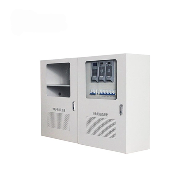
Home distribution boxes typically handle single-phase power supplies and contain 6 to 24 circuits. They include standard circuit breakers for lighting, outlets, and major appliances like water heaters and air conditioning units. A distribution box, also known as a distribution board, electrical panel, or breaker box, is an enclosure that houses electrical components responsible for distributing electricity throughout a building. It receives power from the main electrical supply and divides it into separate circuits, each. A distribution board is a fixed electrical panel that divides power into circuits with protection; a distribution box is more compact or portable, used for junctions or temporary setups. What is a Distribution Board? A distribution board —also called a panelboard, breaker panel, or electrical. This manual is for electronic distribution only and is designed to provide you with the most current information on the Los Angeles Department of Water and Power's (Department) service equipment and installation requirements. Every effort has been made to make this manual as complete and accurate. A distribution box is a key part of electrical systems in buildings. It helps control and distribute electricity to different areas. Today, electrical systems are essential for homes and industries. But what exactly is a power distribution box, and why is it so essential in our daily lives? The DB panel board controls the flow of electricity.
[PDF]

Production equipment represents the fixed assets a company uses directly in the manufacturing process to add value to materials. This definition separates specialized machinery from general items like office supplies or transportation vehicles that do not physically alter the product. These manufacturing machines form the backbone of every production line — cutting, shaping, assembling and packaging components with precision and consistency. From CNC. Manufacturing equipment includes machinery, tools, and automated systems used in production, assembly, and packaging. Regular maintenance ensures efficiency and longevity. Proper management of equipment and utilization of advanced software solutions like HashMicro's Manufacturing Automation Software, can enhance productivity. Factory machines play a crucial role in manufacturing by speeding up production and improving efficiency. Understanding the different types of these machines can help businesses choose the right equipment for their needs. This guide will provide an overview of various factory machines and their. Every physical item is a product of manufacturing, and the machines that create them are the fundamental drivers of this output. This equipment transforms raw materials through precise, repetitive processes into complex finished products. Understanding this machinery is key to grasping how modern.
[PDF]
Security system integration is the process of combining security devices for surveillance, threat detection, and access control into a single, interconnected system. Securitas Technology provides integrated security system solutions for thousands of commercial buildings and corporate campuses in North America. Our. Security Systems and Integration Solutions | L3Harris® Fast. L3Harris' extensive expertise and knowledge supporting system integration is built upon a rich history in the defense, space, civil government and cybersecurity markets with exceptional past performance in security and. Security isn't just about adding more systems — it's about making them work together. We've spent decades addressing. Integrating security systems consists of connecting different technologies (such as CCTV cameras, presence sensors, alarms, access control, remote gates, lighting and app monitoring) so that they work in a coordinated way, sharing data and responding automatically to events. Look Beyond. Get secure operations, seamless scaling, and expert-led Microsoft Copilot Implementation and 24/7 Managed SOC Services. Your business deserves IT that just works. We offer guaranteed outcomes: high reliability, minimal downtime, and strategic maintenance. We free your internal teams to focus purely.
[PDF]

FS offers a full range of PON transceivers for broadband pon networks. Purchase from nearby warehouses. Trusted by 260K+ Enterprise Users. This paper introduces that the construction of urban video surveillance system is an important foundation for realizing urban safety and stability, an important part of the construction of "safe city", and an important carrier of "intelligent city". With the maturity of HD monitoring technology. SFP package with SC /APC receptacle High power 1270 nm DML DFB LD and high sensitivity 1577 nm APD,Support 20km transmission distance with SMF,CML-compatible data input/output interface. Allows configuration of parameters such as PON serial number (ONT ID), Vendor ID, Equipment ID, Logical ONU ID. Technological innovation is the eternal power of human progress, technology has a starting point, no end of innovation! a. ONU series, Wi-Fi, VoIP, CATV,RF, Industrial grade, reverse POE, metal housing ONU optional or mixed model, b. OLTs Series, 2ports, 4ports, 8ports, L2, L3 OLT optional. ONU are. The Fiber OLT's GPON SFP ports are designed for use with the UF-GP-B+ and UF-GP-C+ SFP modules. The GigaPoint® GP1100G is an indoor, 2. 5 Gbps GPON ONU small form-factor service delivery terminal providing one 2. 5 Gigabit Ethernet (GE) interface delivering IPTV video and data services, and one voice line supporting carrier-grade VoIP (SIP). The GP1100G is designed for the industry-leading.
[PDF]

Common methods of protecting busbars include overcurrent-based interlocking schemes, overcurrent-based differential protection, high-impedance differential protection, and percentage differential protection. Interlocking and overcurrent differential protection can be implemented with any suitable. DEFINITIONS. IV EXECUTIVE. Busbar Differential Protection Definition: Busbar differential protection is a scheme that quickly isolates faults by comparing currents entering and leaving the busbar using Kirchoff's current law. Current Differential Protection: This protection method connects CT secondaries in parallel and. Busbars play an important role in power transmission and distribution. They are employed as a central distribution point for all feeders. The problem is that the busbars. Busbars have typically been left without dedicated protection, from the following reasons: It is a fact that the risk of a short circuit happening on modern metal clad equipment is insignificant, but it cannot be completely dismissed. Nevertheless, the damage resulting from one short circuit may be. 25 kV insulation is required. These heat-shrinkable tubes for straight and bent busbars are extremely flexible, allowing them to be easily positioned on busbars and quickly instal ed using a gas torch or oven. They have a high expan-sion ratio, so each size of tubing fits a range of busbar sizes.
[PDF]
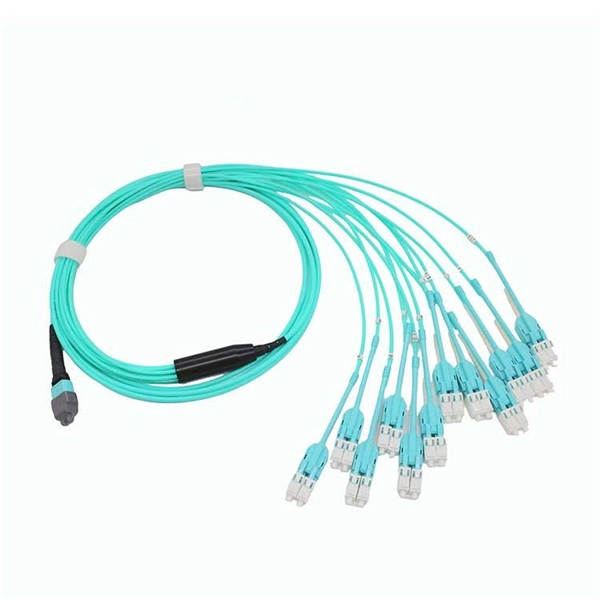
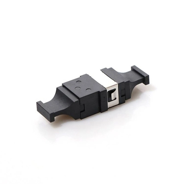
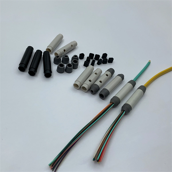
In practice, there are two main ways to terminate fiber optic cable: using a connector to join two fibers to create a temporary, removable joint, or using splicing technology to permanently join two bare fibers directly. Either. Terminating fiber optic cables essentially means putting connectors on fiber optic cable so that you can connect the cable to various devices or network components. Think of it as the equivalent of connecting the dots in a complex puzzle; without proper termination, the whole system can break down. Fiber optic networks are the backbone of modern communication systems, enabling high-speed data transfer and reliable connectivity. When deploying fiber optic cabling, one of the most critical decisions is how to terminate the fiber—either by splicing or using connectors. The process of fiber optic cable termination is the essential act of connecting fiber optic cables to devices, patch panels, or other cables to enable. This Applications Engineering Note explains how different optical fiber termination methods impact the optical performance of telecommunications systems. Optical fiber cabling systems support various communications technologies that use digital as well as analog signaling. This involves either installing a connector or creating a splice to establish a reliable connection point for the optical signal.
[PDF]

This article covers various types of protective relays, such as overcurrent, directional, and differential relays, highlighting their operating characteristics and applications in electrical systems. Different Types of Protective Relays What is a Protective Relay?. Protective relays and devices have been developed over 100 years ago to provide “lastline”of defense for the electrical systems. They are intended to quickly identify a fault and isolate it so the balance of the system continue to run under normal conditions. The selection and applications of. Protective Relay Definition: A protective relay is an automatic device that senses abnormal conditions in electrical circuits and triggers actions to isolate faults. Types of Protective Relays: Protective relays are categorized by their mechanism (electromagnetic, static, mechanical) and function. A protective relay is an intelligent electrical device designed to detect faults in power systems and initiate corrective actions such as tripping a circuit breaker. : 4 The first protective relays were electromagnetic devices, relying on coils operating on moving parts to provide detection of abnormal operating conditions such as. Relion protection and control relays for several application reduce complexity.
[PDF]

Learn how to install a fiber optic termination box step-by-step for FTTH projects. Covers mounting, splicing, routing, labeling, and testing for indoor/outdoor use. Installing a fiber optic termination box is one of those jobs that looks simple on paper. A fiber termination box is the standard instrument used in fiber optic networks to connect, secure, and protect optical fibers at the terminating point. Proper installation and maintenance of FTBs are essential to ensure the reliability and performance of the network infrastructure. Before. FTTP or fiber To The Premises applications have reinforced the importance of reliable and stable fiber optic terminations. Good quality fiber laying and termination systems help achieve minimal back reflection and low signal loss. They also feature resistance to moisture, impact, chemical exposure. New pole mount bracket YK-SX, made by Jera line, to attach and reattach the fiber optic termination boxes, during aerial fiber deployment. No more time losses on reattaching the termination box from the pole. It serves as a critical junction point within a network, providing a centralized and secure. A Fiber Termination Box, also known as a Fiber Distribution Box, is a crucial component in fiber optic networks. FTBs play a vital role in ensuring the.
[PDF]
Choose the right box based on environment (indoor/outdoor), load capacity, and durability. Check for proper IP/NEMA ratings and material quality. Ensure safe placement: install in dry, accessible areas with good ventilation and at appropriate height (typically ~1. Practice good wiring: secure. An electrical distribution box, also known as a power distribution box, panelboard, or consumer unit, is the core of an electrical system. It has three categories: residential, commercial and industrial electrical distribution boxes, all of which play important roles in their respective electrical. When you install a distribution box, you need a variety of tools to get the job done safely and efficiently. To install distribution box systems, you'll use hand tools such as screwdrivers and pliers. Wire strippers are essential when you install distribution box wiring. A measuring tape and. This guide offers an in-depth exploration of installing electrical distribution boards, highlighting essential steps, safety measures, and the integration of business intelligence tools to optimize your work. Just like travelers need clear pathways and safety protocols, your electrical circuits need proper management to prevent chaos. The National Electrical Code (NEC) requirements might seem like bureaucratic.
[PDF]
Step-by-step cable tray and conduit installation method with safety, quality and inspection procedures as per IEEE standards. But before you lay the first tray or clamp down a single cable, you need a solid plan. This guide breaks down the process step by step. Plan the Route Before You Drill No installation should start without a plan. Mark the cable tray route based on your electrical cable tray design and site. This guide covers the critical steps, from selecting the right electrical cable tray and performing accurate cable fill calculations to managing a safe cable pull through and ensuring all bonding and grounding requirements are met. For licensed electricians, mastering these principles is essential. This method statement describes a detailed procedure for properly installing cable trays and conduits for the Feeder System. The objective is to ensure safety, quality and compliance during the. Below is the detailed cable tray installation method statement not only for cable tray but also applicable for GI ladder and trunking for indoor and outdoor applications and in service rooms like pump rooms, electrical rooms and plant rooms etc. The Cable Tray system is installed in electrical rooms, plant rooms, and service corridors. The key requirements for cable tray installation include: Incorrect installation can lead to overheating, cable damage, or system failure. This is why proper planning and execution are.
[PDF]

This video shows real on-site footage of electrical installation, demonstrating safe and standardized wiring methods used by professionals. more Learn how to wire a distribution box step by step!. Temporary power systems are essential for construction projects, yet they often introduce serious safety risks. Loose wiring, exposed connectors, and unstable electrical connections can cause shocks, equipment failures, or costly downtime. This article examines how modern portable power cabinet. work requires electrical power for many purposes. However, exposure to weather, frequent relocation, rough use and other condi-tions not normally encountered with conventional wiring systems necessitate special consideration not require in other applications or in completed structures. The. Metal raceways, cable armor, and other metal enclosures for conductors shall be metallically joined together into a continuous electric conductor and shall be so connected to all boxes, fittings, and cabinets as to provide effective electrical continuity. The requirements of Article 590 apply to temporary power and lighting installations and removals, including. Learn what OSHA requires for temporary wiring on construction sites, from grounding and GFCI protection to overhead clearances and employer liability. Temporary wiring on construction sites must comply with the electrical safety standards in 29 CFR 1926, Subpart K. These federal rules, enforced by.
[PDF]