
Welcome to our channel! In this video, we'll walk you through the process of wiring a home distribution box with a detailed connection diagram. What is Distribution Board? Distribution board. These smaller breaker panels, also known as sub-distribution boards, are commonly used to provide power to secondary circuits within a building. Understanding the components and wiring configuration of an electrical sub panel is essential for safe and efficient electrical installations. In this. Primary distribution systems consist of feeders that deliver power from distribution substations to distribution transformers. A feeder usually begins with a feeder breaker at the distribution substation. Many feeders leave substation in a concrete ducts and are routed to a nearby pole. This breaker must be compatible with both your main system and the additional connections. Typically, a 60-amp or 100-amp breaker will be suitable, depending on the load requirements. It includes isolator, RCCB (Residual current circuit breaker) or RCD (Residual-current device) devices, protective fuses or MCB's (Miniature Circuit Breaker).
[PDF]

In this video, we'll walk you through the process of wiring a home distribution box with a detailed connection diagram. Whether you're an electrician or a DIY enthusiast, this guide will help you understand the basics of home electrical distribution. more Welcome to our. Material preparation: Prepare the required circuit breakers, wires, wiring ties and other materials, and ensure that they meet the design drawings and installation requirements. Location determination: Determine the installation position of the circuit breaker according to the position of the. An electrical panel box, also known as a breaker box or a distribution board, is a crucial component of any electrical system. It serves as a central hub for distributing electricity throughout a building, ensuring that power is delivered safely and efficiently to all the required locations. What is Distribution Board? Distribution board. A distribution board (also known as a service panel or breaker box) is a centralized collection of circuit breakers, fuses, and/or relays used to control and protect the wiring in a home. The diagram of the distribution board's wiring shows exactly how each circuit is wired and connected.
[PDF]
In this video, we'll walk you through the process of wiring a home distribution box with a detailed connection diagram. Whether you're an electrician or a DIY enthusiast, this guide will help you understand the basics of home electrical distribution. more Welcome to our channel! In this video. This guide provides step-by-step instructions for connecting a distribution box and highlights key factors to consider during installation. What Is a Distribution Box? A distribution box, also known as an electrical distribution board, is a critical component in electrical systems. It takes the incoming power and safely distributes it to different circuits throughout your building. However, the key to. A junction box provides a necessary protective enclosure for all electrical wire splices and connections, which must never be left exposed within a wall or ceiling. It serves as a central hub for distributing electricity throughout a building, ensuring that power is delivered safely and efficiently to all the required locations.
[PDF]

Headquartered in Fort Wayne, Indiana, GMS Distribution distributes and sells its products in the United States and Canada. 30 Amp Portable Power Box GMS's Portable Power Distribution Centers have been designed to be the easiest power box you will ever plug in. GMS is focused on the. Our products boast customizable materials and dimensions, ensuring a tailored experience. With a range of materials to choose from and the ability to adjust sizes to your liking, our offerings are designed to meet your unique needs and preferences. American Distribution Boxes are made of high-density polyethylene for years of dependable use. They are non-corrosive, strong, and lightweight for easy handling. Inlet and outlet elevations are positioned to provide equal distribution and meet most local codes. Twist and lock 4” pipe seals and. It is the high-voltage core unit of the American box type transformer, integrating high-voltage load switches, fuses, etc., with a voltage of mostly 15kV. PREMIUM CONSTRUCTION POWER DISTRIBUTION BOX: Crafted by WESTERN, the 6506TLSX Temp power box features a durable blend material for long-lasting performance in demanding environments. ATEK Distribution supplies professional-grade electrical boxes for residential, commercial, industrial, and government projects nationwide. As a certified SDVOSB with 28+ years of experience, we carry every box type you need — correctly specified, fully documented, and ready to ship. Whether you're.
[PDF]
Explore our broad line-up of equipment that generates hydrostatic servo driven pressure - pressure generated by compressing water in a still state. Your complete pumping solution for constant pressure, flow, booster systems, lift stations, and more. Choose from Enclosed Configured or Enclosed Bypass packages, available in UL Type 1, 12, or 3R cabinets, with essential pump features. This range includes equipment that is used in internal pressure fatigue tests of pressure vessels and piping. Sugino has been harnessing the power of. Any orders placed on or before March 31, 2024 will be honored. (excluding blanket orders) The type 350X is a direct replacement for all 3 types and features a significant increase in power and a more advanced brushless DC motor. The Servo team of engineers have created our most powerful and. The A-Series Servo Cylinder is a rod-style, brushless DC electromechanical actuator with built-in controller and Phase Index® absolute position sensor. Providing up to 530 lbf peak force and up to 7. 75” of travel, the Servo Cylinder was designed from the ground up to be extremely robust and very. integrally cast. Frame sizes 71 - 160 have pedestals t at are removable. Pressure die cast aluminum frame sizes re from 56 - 160. The SV3 Series servo system supports EtherCAT®, a globally popular Ethernet protocol. To enhance next-generation machine performance, the motor features a 26-bit encoder resolution and a.
[PDF]
Engineers involved in the design, characterization and validation of Universal Serial Bus Revision 2.0 (USB 2.0) devices face pressure to speed new products to market. Tools are available to help them quickl.
[PDF]

In this guide, you will find a chronological description of the fusion splicing process, the principal technical standards, and answers to the real-life questions network engineers and procurement teams may have. In this guide, we cover the basics of fiber optic splicing, how to perform splicing using two different methods, and finally some best practices to perform good fiber splicing. What is Fiber Optic Splicing and Why is it Needed? – #1. Use and Maintain Your. This Geoschematics drawing remains easy to read despite containing more than 2000 fibers and 500 splices. Splice Diagrams or Matrices capture an electric or optical network inside a location – documenting cables, ported equipment, and connections. Splices are fiber-to-fiber, port-to-fiber and. This guide will walk you through the complete process of fiber optic splicing—covering each step in detail so you can deliver a clean, professional splice every time. Before jumping into the physical steps, it's important to understand the two primary methods of fiber splicing: fusion splicing and. Page 1 The FOSC 450 fiber optic splice closures use compressed-gel cable seals to environmentally seal fiber cable splice points. FOSC 450-ab-c-dd-e-fgh The maximum single splice capacity of the FOSC 450 B6 closure is a = Closure size 144 with 24 splices stored on six trays. Therefore, we will also touch on cost factors, risk management, and best practices in.
[PDF]

6 core Fiber Optical Splicing With 24 Port LIU || Full Installation || Beginner Watch this video Fiber optic splicing is the process of joining two fiber optic cables together to create a conti. more. In this article, we'll explain how to connect multiple Ethernet switches using fiber optic cables and the equipment required for this to work. Network topology refers to the way in which the links and nodes of a network are arranged in relation to each other. Simply put, it defines how network. Choose an SFP module based on the fiber optic cabling that will be connected to the network switches. SFP transceiver modules almost always require two fiber optic cable strands. Most modern SFP transceiver modules. Most modern fiber-enabled network switches require an SFP transceiver module featuring a duplex (two strand) multimode OM3 or duplex single mode OS2 connection with LC connectors. Direct attach cables with pre-terminated SFP connections may also be used. Download the Application PDF SFP transceiver. This article will guide you through the necessary tools, materials, and methods on how to connect fiber optic cables effectively, ensuring you achieve optimal performance from your fiber optic network. These diagrams help engineers plan infrastructure for residential and commercial buildings. By using light signals, fiber optics provide faster speeds and better reliability than.
[PDF]

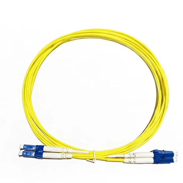
This guide will walk you through the most common fiber connector types, explaining their characteristics, advantages, and typical use cases. An optical fiber connector is a device used to link optical fibers, facilitating the efficient transmission of light signals. An optical fiber connector enables quicker connection and disconnection than splicing. Whether you're planning an FTTH deployment, upgrading a data center, or working in telecom infrastructure, this guide will help you make informed decisions. This guide provides a fully updated and industry-ready overview of LC fiber optics, explaining the origin and design of LC connectors, their key features, and the complete ecosystem of LC-based products used in modern networking. It covers LC connectors, LC patch cables, uniboot designs, armored. Fiber connector types LC, SC, FC, ST, MTP, and MPO are widely used in past and present. What are the differences between them? Who is the most popular one? Find the answer in the article. What is a Fiber Connector? The optical fiber connector is a kind of detachable passive optical component used. The answer often lies in tiny but mighty components called LC connectors. There have been many types of connectors developed for fiber cable. Single mode networks have used FC or SC.
[PDF]

This guide covers everything: what fiber optic pigtails are, how they differ from patch cords, which connector and polish type to specify, how to choose between mechanical and fusion splicing, and the real-world applications where pigtails are the right call. In this guide, we cover the basics of fiber optic splicing, how to perform splicing using two different methods, and finally some best practices to perform good fiber splicing. What is Fiber Optic Splicing and Why is it Needed? – #1. Whether you're building out an ODF. Think of a fiber optic cable splice as the seamless stitching that keeps data flowing through the delicate threads of a network—like a master tailor joining fabric with precision. Whether repairing a broken cable or extending a fiber run, fiber optic splicing ensures light signals travel. Fibre optic splicing is an essential skill in the world of modern telecommunications, offering a reliable method to connect optical fibres for seamless data transmission. As the demand for high-speed internet and robust communication networks continues to grow, learning to splice fibre optics is. In this guide, you will find a chronological description of the fusion splicing process, the principal technical standards, and answers to the real-life questions network engineers and procurement teams may have. Therefore, we will also touch on cost factors, risk management, and best practices in.
[PDF]

In this paper, various operational factors affecting 100G transmission over G. D fiber-cables are discussed to make the right fiber selection for the long-haul network. Selecting appropriate G. 652 fibre was originally optimized for use in the 1310 nm wavelength region but can also be used in the 1550 nm region. This is the latest revision of a Recommendation that was first created in 1984 and deals with some relatively minor modifications. a number of concatenated cable. G. 92% of. Fiber optic cables are the ultimate technology used in data transfer using light waves. They are classified based on wavelength band, core/cladding size, application, and compliance with international standards such as IEC, ITU-T, and TIE/EIA. In the next sections, the real artwork is putting on. This guide explains the most important ITU-T G. 655—to help you make an informed decision for your project, whether it's a long-haul backbone or a final FTTH drop. In the world of fiber optics, not all glass is created equal. The core of every cable—the optical. Because GPON and XGS-PON are deployed in diverse environments, fiber-containing components such as PLC splitters must be evaluated not only by their standard parameters but also by their sensitivity to bending loss, which is critical for maintaining stable optical transmission. The ITU-T defines.
[PDF]
Coherent optical module refers to a typically hot-pluggable coherent optical transceiver that uses coherent modulation (//) rather than amplitude modulation (RZ//) and is typically used in high-bandwidth data communications applications. typically have an electrical interface on the side that connects to the inside of the system and an optical interface on the side that connects to the outside world through a fiber optic cable. The technical details of coherent op.
[PDF]

Mechanical Optical Switches: Switching times typically range from 1-10ms, suitable for long-distance transmission scenarios where latency is not critical (such as backbone network protection switching). Solid-State Optical Switches: Based on thermooptic or electrooptic effects, response. We lead the industry in optical switch technology, delivering the lowest insertion loss (0. 2 dB), fastest switching speed (10 ns), broadest wavelength range (300–2400 nm), widest fiber compatibility, highest optical power handling (50 W), and space-qualified reliability. Backed by over 25 years of. Use this optical switches buying guide to compare major types, define selection criteria, and find suppliers: Professional purchasing of high-value photonics products is a substantial responsibility, where a structured decision-making process is essential. RP Photonics offers a lot of help: Get. This document is a troubleshooting and selection guide for common optical switch failures, compiled based on over 500 field cases. These switches are built on proven, reliable optomechanical technology that has seen more than 30 years of successful operation. Each. The POLATIS ® Series 7000 384x384 all-optical circuit switch is designed to meet the most demanding applications with exceptionally low optical loss, compact size, and fast switching speeds. With support for Software-Defined Networks (SDNs) via embedded NETCONF and RESTCONF control interfaces, the.
[PDF]

