
Connect the red wire to the copper wire with the red color bar of the optical/electrical composite cable, and connect the black wire to the other copper wire of the optical/electrical composite cable. Then press and secure the crimp tube. Ensure that no copper. The composite fiber optic cable is a type of cable that combines both fiber optic and copper conductors within a single cable sheath. This hybrid construction allows for the simultaneous transmission of data using fiber optics and electrical power or additional data using copper conductors. How to Use the Composite Fiber Optic Cable? To begin, you need to gather all the accessories and equipment required: 1. Waterproof Industrial-Grade Fiber PoE Media Converter Compatible with the IEEE802. Cut the cable along the center and pull one copper cable on the left and right sides to the position shown in the figure to expose the optical fiber. Whether you're a seasoned technician or a beginner, this guide has something for everyone. more In this video, we'll walk you. In a previous blog, we covered what to do when you need to connect a device that is located beyond the 100-meter distance requirement and described four ways to address the problem—a new TR, the use of an extender device, extended-reach copper cable and fiber. This article will guide you through the necessary tools, materials, and methods on how to connect fiber optic cables effectively.
[PDF]
These modules are designed to transmit 100G Ethernet signals across single-mode fiber over distances up to roughly 80 kilometers. The “BiDi” concept, short for bidirectional transmission, means that a single fiber strand carries traffic in both directions using different. The 80km SFP is a compact, hot-pluggable optical transceiver module standardized for long-distance fiber optical communication, with a maximum single-fiber transmission distance of 80 kilometers as its core performance indicator. It is designed to meet the interconnection needs of medium and. SFP (Small Form-factor Pluggable) modules have evolved beyond short-reach Ethernet, enabling reliable 80km and 120km links with optical performance, wavelength management, and power efficiency. This guide dives into the practicalities of 80km and 120km long-haul SFP modules, including key. It can reach up to 80km using single-mode fiber. This module is small and easy to swap. You can change it without turning off your network. The QSFP28-100G-ZR4 uses LAN-WDM technology. It sends many signals through one fiber. This makes your network. Cisco ® QSFP28 100G ZR extends 100GbE coherent links from QSFP28 ports reaching up to 80km over dark fiber and up to 300km over amplified Dense Wave Division Multiplexing (DWDM) links.
[PDF]

It transforms high volumes of electrical signals into optical signals for transmission over fiber cables, or reverses the process at the receiving end. Think of it like a Type-C to USB adapter in everyday tech—its core function is seamless conversion between electrical and optical. Optical modules are compact devices that convert electrical signals into optical signals and vice versa. They are used in fiber optic communication systems to transmit data over long distances with minimal loss and interference. These modules typically consist of a laser or LED transmitter, a. In the world of fiber optic communications, optical transceiver modules play a pivotal role as interfaces that convert electrical signals to optical signals and vice versa. An optical module works at the physical layer of the OSI model and is one of the core components in the fiber communication. The frequency response characterization of these electrical-to-optical (E/O, modulators sometimes integrated with lasers) and optical-to-electrical (O/E, photo detectors and receivers) converters can be important in terms of such parameters as bandwidth, flatness, phase linearity and group delay. The optical module serves as a crucial component in optical fiber communication systems, operating at the physical layer, which is the lowest layer in the OSI model. Among various optical module form factors, SFP (Small Form-Factor Pluggable).
[PDF]
This integration is achieved through the use of wavelength division multiplexing (WDM) filters, which separate the transmit and receive wavelengths within the same fiber. These modules play a vital role in transmitting and receiving optical signals. TOSA ( Transmitter Optical Sub-Assembly), converts electrical signals into optical signals for transmission. In this mode, the WDM system transmits multi-wavelength optical signals in receive and transmit directions through separate fibers. Simple design and low requirements. If you're dealing with data centers, telecommunications, or AI networking, grasping the key parameters of an optical. In the era of 5G, AI, and high-speed data centers, optical modules serve as the core bridge for converting electrical signals to optical signals (and vice versa), enabling fast, reliable data transmission across networks. Among various optical module form factors, SFP (Small Form-Factor Pluggable). Fiber optic transceivers are key components of the fiber optic transmission network. They are designed in small form-factor with some integrated optical sub-assemblies which can be suitable for the high-density network. There are many SFPs available in the market with different features and. Most systems operate by transmitting in one direction on one fiber and in the reverse direction on another fiber for full duplex operation.
[PDF]
GPON is an alternative to Ethernet switching in campus networking. GPON replaces the traditional three-tier Ethernet design with a two-tier optic network which eliminates access and distribution Etherne.
[PDF]

10 Gigabit optical transceivers have higher speed and better performance than Gigabit optical transceivers. However, compared with Gigabit optical transceivers, the price of 10 Gigabit optical transceivers is also more expensive. While they function similarly, there are many differences in price. This. Gigabit optical modules have a wide range of applications in enterprise networks, data centers, and video transmission, and are seen as a solution that balances bandwidth and cost. Demand for gigabit optical modules still dominates the current networking market. It is widely used in various types. SFP+ modules support the following data rates: 1 Gbps. Many SFP+ modules are backward-compatible with SFP transceivers that support slower data rates. SFP+ modules are specified for. When shopping for optical modules, we need to compare different specifications of optical modules and choose the model that suits our application from to ensure that it is compatible with our equipment and meets our needs. In this article, we will conduct a comparative analysis of 10 Gigabit.
[PDF]

This procurement guide curates leading SFP module manufacturers and suppliers in Europe, summarizes their differentiators, and offers practical buying tips. ESTEL designs and manufactures high‑performance optical transceivers in Europe and in the US, with local technical support and a secure supply chain. Our optical modules power demanding telecom and datacom networks across data centers, metro and long‑haul links. Browse optical transceivers Talk to. Transceiver stands for Transmitter/Receiver Module. These (opto-)electronic devices allow data transmission over copper and fiber cables. A wide range of form factors are available allowing data rates from 100Mbps up to 800Gbps. Skylane Optics offers the full range of transceivers with an unique. We are committed to providing high-performing optics and transceivers through professional and reliable capabilities. Equipped with the most extensive and stringent testing and solution designing processes. Delivered fast, tested, and 100% compatible with your hardware. Swedish Telecom Opto is built for scale — not single-click sales. We work with mid to large organizations, supporting. There are 317 Optical Products Manufacturers in Southern Europe as of August 15, 2024; which is an 1. 26% increase from 2023. With over two decades of experience in the industry, we specialize in designing and producing high-quality optical components for a wide range of applications. Our team of skilled engineers and technicians are.
[PDF]

The process involves a combination of national infrastructure, local engineering, and property-level setup. In this guide, we'll break down the fiber installation process from start to. This guide walks you through the complete fiber installation process, from checking availability to optimizing your Wi-Fi network performance. Fiber transmits data using light signals through glass strands, delivering faster speeds and lower latency than cable or DSL connections that rely on. In this article we'll break down how fiber internet is installed - from the network fiber drop outside your house to the in-home setup with your router and gateway - and what you should expect at each stage. Fiber optic internet is generally installed in the following 5 steps, which we'll dive. Want lightning-fast internet at home? Fiber optic installation is the way to go! It's super reliable and perfect for streaming, gaming, or using multiple devices. This guide breaks down the process in easy steps so you know what to expect. BCS Consultants, a trusted fiber optic installation company based in California, provides end-to-end fiber optic services, including expert planning. However, setting up a fiber optic connection to your router can seem daunting if you're unfamiliar with the process. In this guide, we'll walk you through how to connect a fiber optic cable to a router safely and efficiently. Why Use Fiber Optic Internet? Before diving into the setup, let's quickly.
[PDF]

This article explains the modulation formats used in coherent optical systems (QPSK, 8/16/64-QAM), how DSP and OSNR tradeoffs determine reach vs. capacity, why probabilistic constellation shaping (PCS) matters, and how pluggable coherent modules (QSFP-DD / ZR / ZR+). A coherent optical module (Coherent Optical Module) is an advanced optical transceiver that utilizes coherent optical communication technology to encode and transmit data by manipulating multi-dimensional information such as the amplitude, phase, and polarization of light. Unlike traditional. Co-packaged optics (CPO) has emerged as an ultimate solution for achieving the ultra-high bandwidths, shoreline densities, and energy efficiencies required by future GPUs and network switches for AI. Among these challenges, power efficiency. ong-haul coherent optical communications systems. Due to limitations in space, it focuses mainly on coherent optical systems usin major milestone in long-haul transmission [1, 2]. Coherent receivers were intensively studied in the eighties [3–7] because of their superiority to their. =============================================================================== QSFP-DD Connector =============================================================================== Description : -Interface : 8/1/c7 FP Number : 2. Diag Capable : yes Number of Lanes : 1 Connector Code : LC.
[PDF]

First, connect each pre-terminated fiber optic cable to the adapter panel separately, making sure the ports correspond one-to-one; then fix the fiber optic adapter panel to the front panel of the distribution box with the bend radius control clip. In general, installing the optical fiber distribution box can be divided into three steps: installing the optical fiber distribution box on the rack, introducing the optical cable into the optical fiber distribution box, and planning the optical fiber path in the optical fiber distribution box. The. Bottom installation: Select a proper installation position in the equipment room and drill four holes in the floor according to the dimensions shown in the manual. Fix the rack to the ground with expansion bolts. Top installation: Dimensions of four connection holes on the top according to the. The Optical Distribution Box (ODB) is high-density 2-in-2-out fiber box solution. Designing with a compact size of 340x220x100mm, the cabinet accommodates 1x2,1x4,1x8 and 1x16 etc. The 4 ports are sized for main cable from 9 to 16mm in diameter, along with 16 3mm cables. Accessory Kits:. Install the optical fiber distribution box on the rack. Ensure that the box is installed firmly and horizontally, and the deviation of perpendicularity is not greater than 3mm.
[PDF]

This article will give you an overview of the use cases for fiber-optic networking, some of the terms used in fiber networking, and suggestions for setting up a fiber network. Once you understand the basic concepts, you can check out my Recommended Equipment section toward. Fiber tapping is a network tap method that extracts signal from an optical fiber without breaking the connection. Tapping of optical fiber entails diverting some of the signal being transmitted in the core of the fiber into another fiber or a detector. Fiber to the home (FTTH) systems use beam. Optical fiber is a technology used to transmit data by sending short light pulses along a long fiber, which is typically made of glass or plastic. In optical fiber communication, metal wires are preferred for transmission because the signals travel more safely. Optical fibers are also resistant to. Photo: Light pipe: fiber optics means sending light beams down thin strands of plastic or glass by making them bounce repeatedly off the walls. This is a simulated image. Note that in some countries, including the UK, fiber optics is spelled "fibre optics. " If you're looking for information online. This manual covers everything about fiber optic cables, how they work, where they are used, and what is new in this area of technology. The choice of fiber optic cable depends on the specific needs of the application, as well as the.
[PDF]
An optical power meter (OPM) is a device used to measure the power in an signal. The term usually refers to a device for testing average power in systems. Other general purpose light power measuring devices are usually called,, power meters (can be sensors or ), or lux meters. A typical optical power meter consists of a , measuring and display. The sens.
[PDF]

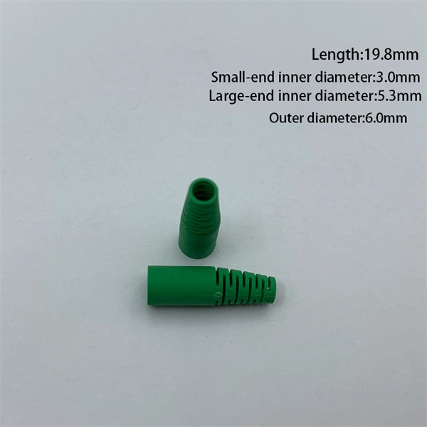
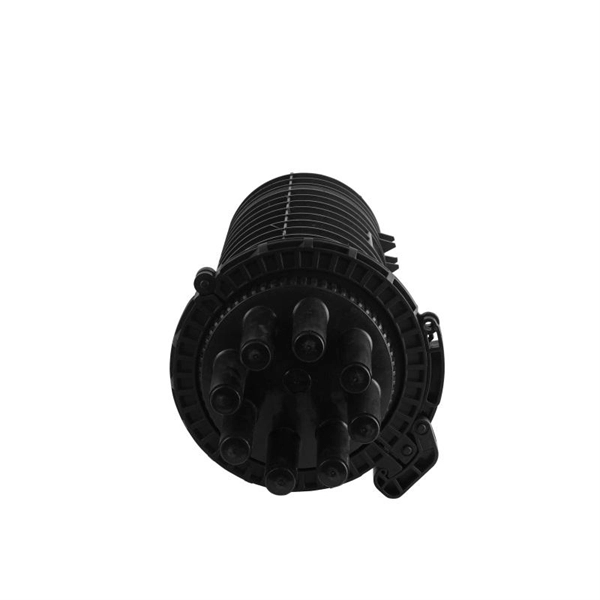
Strip the cable the required length, minimum 0. 5 meter or more, to establish easy and safe installation with enough buffer size. Pass the stripped cable into the upper side of the splice tray. Fix the cable strength member (3) on part (2) and stabilize with cable fixing part. To establish easy and safe installation put the box where it will be installed and measure the required length of the cable. 5 meter or more, to. Lockable Cable inputs: 2x 12mm - 16x Space for 1x16 SC splitter or 1x32 LC splitter 1. Cable fixing Instert the stripped cable through the cable entry port and fasten the FRP element(s) to the block. The outher coating should be fasten useing the steel hops. Do not fasten too. Stripping and preparing fibre optic cables for termination is a critical step in the installation and maintenance of fibre optic networks. Firstly, it is important to consider that when stripping multi-layer cables for connectorization, each layer must usually be stripped individually, as they all usually need to be stripped to different lengths. Cutting and stripping the cable jacket can be done with a special fiber stripper or a properly set wire stripper as long as it does. Whether it is indoor or outdoor fiber-optic (FO) cable, using a step-by-step approach reduces the chance of fiber damage while ensuring the performance of fibers. In our continuing discussion of installing FO cables, let's use a step-by-step approach in detailing how to strip and clean indoor and.
[PDF]

