While a cut or damaged fiber optic cable can temporarily take your network down, it is possible to quickly fix the cable with the right tools. This wikiHow article will teach you how to splice a cut fiber optic cable back together with a fiber optic stripper and cutter and a fiber. To connect your fiber optic cable to a router, ensure you have the following: Fiber optic modem (ONT): Most fiber connections require an Optical Network Terminal (ONT), provided by your ISP. Compatible router: Verify that your router supports fiber optic input (look for an SFP or WAN port labeled. The fiber optic cable does not plug directly into a standard home router because the signal type must be translated. The fiber line terminates at the Optical Network Terminal (ONT), which is typically supplied and installed by the internet service provider. This specialized equipment serves as the. The process to connect fiber optic cable to router requires careful attention to detail, but I'll walk you through every critical step with the precision and clarity you deserve. Here's a step-by-step guide to help you through it. Understand the Basics Before diving in, familiarize yourself with the components involved:. See you soon! 🚀 How to connect a fiber optic cable to the router. Check compatibility: Before you begin, make sure your router supports fiber optic connection. Not all routers can connect directly to a fiber cable, so it is important to verify this information before continuing.
[PDF]

See this topic to learn how to remove and install a door. Unlock and open the door. Removing a door Hold the door in place, and lift both hinge pins until they lock in the open position so that the door is disengaged. Remove the door from the rack cabinet frame. Install. Before installing your server in a rack cabinet, review the following guidelines: Two or more people are required to install the device in a rack cabinet. Ensure that the room air temperature is below 35°C (95°F). Do not block any air vents; usually 15 cm (6 in. ) of space provides proper airflow. In this comprehensive guide, we will walk you through the step-by-step process to ensure a successful installation and setup of your network cabinet system. Key steps include measuring the installation area, mounting rails, organizing cables, and testing stability. Proper grounding and compliance with safety. Page 3 M3. Click Side Panels (E) into place. To install the Tempered Glass Door (G), locate the side with two pins. With your thumb, pull down on the spring pin and slide it. Complete Assembly Procedure for 9U Wall Mounted Network Cabinet (Double Section) How to assemble a double section wall mounted network cabinet server rack? 1, Insert top and bottom panels into the side frames. And fixed the frame on the front door position with 4 M5*8 self-tapping screws.
[PDF]

In this video we will learn how to configure cisco core switch active active using HSRP step by step. In this LAB we practice on creating vlan, distribute vlan to other switch in our network, creating interface vlan and assign IP address for layer 3 routing. Follow these simple best practices to set up a new network switch. Just like riding a bicycle, nobody's born knowing how to setup a network switch. And this process is a little more advanced than, say, setting up your home Internet or even a plug-and-play type switch. But, with the right guidance. Looking to configure a Cisco switch for the first time? If the answer is YES, you're in the right place. You're going to configure: SSH access with local AAA authentication. Here's a network diagram, so you can follow. When you deploy a new switch, it's important to configure it properly to ensure optimal performance, security, and functionality. It comes with an IOS. An IOS is a Cisco proprietary operating system. It allows you to configure, customize, and use Cisco devices as needed. It includes thousands of commands for various tasks. This tutorial explains essential. Although a Cisco switch is a much simpler network device compared with other devices (such as routers and firewalls for example), many people have difficulties to configure a Cisco Catalyst Switch. Configuring a Cisco switch is a fundamental task for network administrators, as it lays the groundwork for.
[PDF]

Our guide delivers actionable, step-by-step best practices for rack layout, cable management, and patch panel installation. Following these steps helps you build a clean and efficient structured cabling system that simplifies maintenance and maximizes network performance. Patch panels are one of the best ways to manage an expansive local area network (LAN) by providing quick and easy access to the ports and connections that connect them altogether. Before a single cable is. H. Use cabinet screws to fix the network patch panel to the network cabinet. Note the wiring sequence on the patch panel when wiring, as T568A and T568B have different sequences. Different brands of patch panels may also have different wiring sequences, so always pay attention to the sequence. A patch panel is a board that houses multiple network ports. It acts as a bridge between incoming and outgoing Ethernet cables. Instead of plugging and unplugging devices directly from network switches, you connect them to the patch. Patch panels are a crucial component in any network infrastructure, providing a centralized location for managing cables and connections. By using patch panels, network administrators can simplify cable management, improve network scalability, and reduce downtime. This innovative tool combines precision with automation, ensuring accurate network documentation for IT professionals and network administrators.
[PDF]

Start by separating your Ethernet cable into two separate cables and connecting them to the back of the Ethernet cable splitter. Once the cables are securely connected, connect the other ends to your desired devices. Ensure that the cables are tightly secure and that all connections. When you need to connect multiple wired devices like computers, printers, and IP phones, but only have one Ethernet wall port, using an Ethernet splitter or network switch can expand your connectivity without rewiring. This guide explains your options and helps you choose the best solution for your. An Ethernet splitter is a small device that allows two Ethernet-connected devices to share a single cable run. It does not increase speed or create extra bandwidth. It simply divides signal pairs. This tool works best in basic setups where running another cable is not possible. An Ethernet splitter. Ethernet cable splitter wiring diagrams are essential for anyone who needs to connect multiple devices in a home or office network. With the ever-increasing popularity of high-speed internet and streaming services, providing reliable connections to multiple devices is becoming increasingly. An Ethernet splitter doesn't actually split a single Ethernet connection to provide separate internet access to two devices. Instead, it utilizes only two of the four pairs of wires within a single Ethernet cable to connect two devices, requiring two splitters for the setup to function correctly.
[PDF]

This comprehensive guide will explore the importance and benefits of this integration, provide an understanding of fiber optic cable and Ethernet ports, discuss their compatibility, and offer a step-by-step process for connecting them. Proper connection of fiber optic cables is essential to harness these benefits fully, as even minor errors can lead to significant performance issues like signal loss. This article will guide you through the necessary tools, materials, and methods on how to connect fiber optic cables effectively. But here's the thing: how you connect fiber optic cable really matters. A shaky connection means weaker signals, dropped streaming, or slow uploads. Get the hookup right, and you'll enjoy streaming, gaming, and video calls without interruptions. Fiber optic cables need careful handling. Unlike. The process to connect fiber optic cable to router requires careful attention to detail, but I'll walk you through every critical step with the precision and clarity you deserve. Why Use Fiber Optic Internet? Before diving into the setup, let's quickly recap why fiber optics are worth the effort: Lightning-fast speeds (up to 1 Gbps or higher). Low latency for. Connecting a fiber optic cable to an Ethernet network involves a few key steps and requires some specific hardware to ensure a seamless transition between these two different types of network mediums.
[PDF]

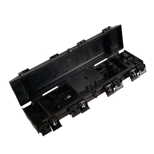
This complete guide covers everything from identifying causes of failure to advanced repair techniques, drawing on the latest industry standards and innovations. A fiber termination box is the standard instrument used in fiber optic networks to connect, secure, and protect optical fibers at the terminating point. Proper installation and maintenance of FTBs are essential to ensure the reliability and performance of the network infrastructure. Before. By understanding these key elements and following the outlined steps, you can effectively repair fiber optic cables and maintain the high-performance network necessary for today's demanding communication needs. Whether you're a network technician, IT professional, or telecom operator, you'll find practical steps, tools, and tips to restore. FTTP or fiber To The Premises applications have reinforced the importance of reliable and stable fiber optic terminations. Good quality fiber laying and termination systems help achieve minimal back reflection and low signal loss. They also feature resistance to moisture, impact, chemical exposure. A fiber optic distribution box, also known as a fiber optic terminal box or fiber optic termination box, is a device used to connect and manage fiber optic cables in a network. The distribution box provides.
[PDF]

They are used to connect two fiber optic cables with different connectors or to change the connector type of a cable. In this article, we will discuss how to use fiber optic adapters, product selection, engineering applications, and precautions in use. Fiber optic adapters, also known as couplers, play a crucial role in fiber optic networks by providing a connection point between two fiber optic connectors. Using the wrong type or neglecting cleaning can lead to signal loss and unstable connections. In this guide, we'll explore what fiber optic adapters are, their main types, how to choose the. Fiber optic adapters play a critical role in ensuring stable and low-loss fiber connections. This guide covers adapter types, selection criteria, cleaning tips, FAQs, and B2B customization options to help businesses build reliable and scalable fiber networks. It ensures precise alignment between fibers and facilitates effective transmission of optical signals. Without the proper adapter, signals can degrade or become unstable, which can dramatically decrease the reliability of a network.
[PDF]

In this video, we'll show you how to connect an energy meter to a distribution board (DB) safely and efficiently. A residential electric meter box wiring diagram illustrates the connection between the utility service drop and the main breaker panel. It shows the hot wire entering the meter lugs, the neutral wire connecting to the neutral bus bar, and the essential ground wire linkage to ensure system safety. energy meter connection with distribution box How to Connect an Energy Meter to Your Distribution Box Easily Steps to Properly Connect Your Energy Meter to a Distribution Box. This prevents arc faults and ensures safety when modifying or inspecting current paths. Inside the service housing, line conductors from the utility feed typically enter through the. The wiring that links the utility company's service point to a home's electrical distribution system is the main service connection. This “meter to panel” wiring establishes the pathway for all incoming electrical power from the grid to the home. Whether you're an electrician or a DIY enthusiast, this guide will help you understand the basics of home electrical distribution. What is Distribution Board? Distribution board.
[PDF]
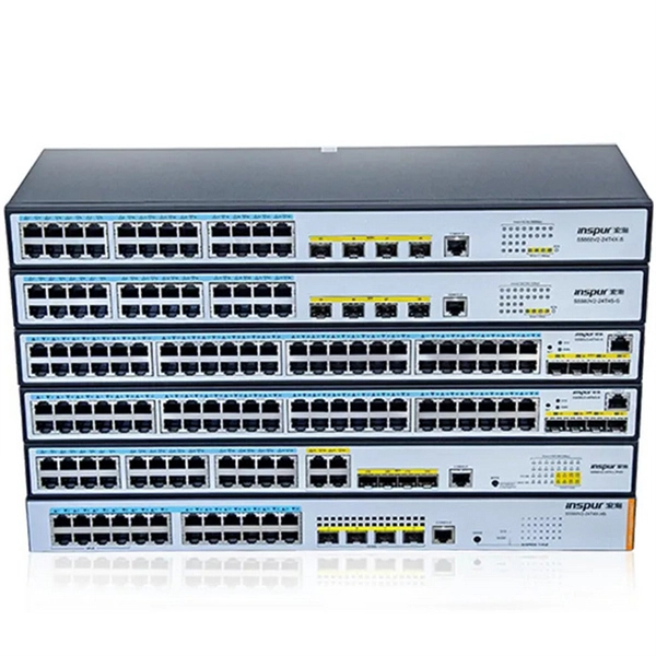
You can access the switch through the serial console port or the Mini USB console port. Only the Mini USB console port is available if you connect both the serial console port and Mini USB console port. This chapter describes how to connect your switch to a network. In this video tutorial I show you How to configure Access Port in H3C switch, how to configure Trunk Port in H3C switch, How to All. more Hello Friends, In this video I will show you H3C Switch Configuration. On the switch, you can configure Telnet or SSH for remote access through Ethernet ports.
[PDF]

This guide will explain their functions, discuss the role of single-mode LC connectors in modern fiber optic systems, and present the logic for their adoption on a broader scale. Proper connection of fiber optic cables is essential to harness these benefits fully, as even minor errors can lead to significant performance issues like signal loss. This article will guide you through the necessary tools, materials, and methods on how to connect fiber optic cables effectively. Fiber optic internet delivers blazing-fast speeds and reliable connectivity, making it a top choice for modern homes and businesses. In this guide, we'll walk you through how to. In this article, we'll explain how to connect multiple Ethernet switches using fiber optic cables and the equipment required for this to work. Network topology refers to the way in which the links and nodes of a network are arranged in relation to each other. There are also fiber-to-fiber versions that translate between different fiber types, wavelengths, or distances. Common families support 10/100/1000 Ethernet and. This is where single-mode fiber optics comes in. Single-mode fiber is being viewed as the backbone of enterprise connections, and it is used to facilitate all 400G solutions and real-time AI solutions/applications, due to its ability to transmit data over long distances with minimal signal loss.
[PDF]

Learn how to splice fiber optic cable using fusion splicing with this complete step-by-step guide. Includes tools, best practices, loss standards (ITU-T G. 652), cost analysis, and FAQs for network engineers and installers. Fiber optic cables can be connected together using a couple of different methods: 1. Fusion Splicing: This method involves aligning the ends of the two fiber optic cables and then fusing them together using heat. This creates a permanent and low-loss connection. This article will guide you through the necessary tools, materials, and methods on how to connect fiber optic cables effectively. Fiber optic adapters, also known as couplers, play a crucial role in fiber optic networks by providing a connection point between two fiber optic connectors. They enable seamless and reliable optical signal transmission between different fiber optic cables, connectors, or devices. Regardless of the type of fiber network you're deploying, be it for telecom, enterprise data centers, or smart city infrastructure, fusion splicing provides the benefits of. Mastering the art of connecting two optical fibers is essential for ensuring optimal network performance and stability. The connector is made and well test. Simply plug and play. However, the length is fixed with a pre-made fiber optical cable. You can't get all the length you need. In this video, you will see how to use the LC coupler to join two.
[PDF]
Optical Fiber Cable & Accessories Price in Nepal, Kathmandu. Buy with best and reasonable price @ ITShop Nepal. Nepal - Shop for Best Online at Daraz. np Wide Variety of fiber optical cables. Great Prices, Even Better Service. Copyright © 2026 Janaki Cable Industry. Powered by one tech® View the latest retail rates for Janaki Cable products effective from Apr 20 2026. Includes per-meter prices for Copper/Aluminum Armoured Power Cables, Multistrand Flexible Wires, and FRLS Cables. The Nepalese optical fiber cables market fell slightly to $X in 2025, dropping by X% against the previous year. This figure reflects the total revenues of producers and importers (excluding logistics costs, retail marketing costs, and retailers' margins, which will be included in the final consumer. SÜRGÜLÜ PATCHPANEL SC UPC DUBLEX 24XADAPTÖR 48XPIGTAIL RAL7035 1u 19” MEK. SÜRGÜLÜ PATCHPANEL SC UPC DUBLEX 12XADAPTÖR 24XPIGTAIL RAL7035 Buy Fiber Optic Infrastractures and Accessories in Nepal at best price from platforms Hub. is a leading Internet & TV service provider in Nepal. Since 24 years, Vianet Communication has always remained at the forefront, providing reliable and affordable Fiber Broadband Internet Services.
[PDF]
