
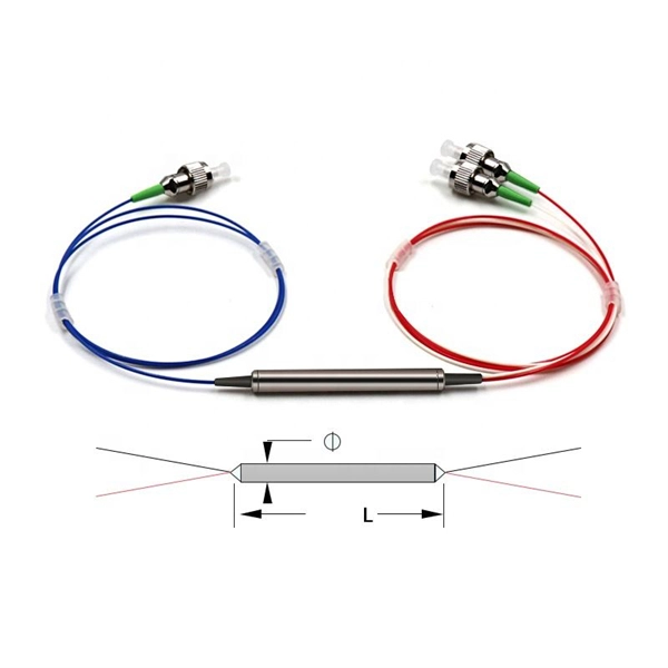
In this guide, you will find a chronological description of the fusion splicing process, the principal technical standards, and answers to the real-life questions network engineers and procurement teams may have. TMM P021 OPTIC FIBRE CABLE JOINING, TERMINATION & MANAGEMENT Version 9. Therefore, we will also touch on cost factors, risk management, and best practices in. Fusion Splicing • Splicing is the process of connecting two bare fibres directly without any connectors. • Splicing provide much lower insertion loss compared to fiber connectors that's why Splicing is preferred over the use of Connectors. Fiber mechanical splicing – Insertion loss < 0. 5dB Fiber. What is Fiber Optic Splicing and Why is it Needed? – #1. Ensure Your Splicing Tools are Clean – #2. 56 was approved by ITU-T Study Group 6 (2001-2004) under the ITU-T Recommendation A. 8 procedure on 14 May 2003. The International Telecommunication Union (ITU) is the United Nations specialized agency in the field of telecommunications. By following the step-by-step guide provided, you can effectively perform fusion splicing to maintain high-quality fiber optic.
[PDF]

This paper provides practical guidance on preparing your edge sites including how to assess the site's constraints as well as, power, cooling, and network connectivity needs. It also provides guidance on starting up the system. Micro data centers offer a compact, cost-effective alternative to traditional facilities, bringing critical compute and storage closer to where it's needed. Image: Alamy Building a full-scale, traditional data center requires millions of dollars and many months of construction. The focus of this paper is on small server rooms and branch offices. The Micro Data Center design addresses the need for a structured approach to implementing robust, integrated and secure networks in the industrial space. Adhering to Converged Plantwide Ethernet (CPwE) principles, the MDC design represents the basic requirements of the manufacturing environment. designing data centers. Many data centers around the world rely on our fiber-optic and twisted-pair cabling solutions as the physical foun ation of their networks. R&M's Automated Infrastructure Management (AIM) system has also become the basis for automating and orchestrating all MAC processes. This document describes the site requirements for installing the FusionModule2000 6. 0 smart modular data center (smart module for short) as well as the methods for installing cabinets, devices, and cables, providing installation guidance and technical support for onsite installation personnel and.
[PDF]

This procedure provides general information for installing all Corning Optical Communications Solo® ADSS All-Dielectric Self-Supporting fiber optic cables from 2-288 fibers. This document provides installation instructions for the Cisco Coarse Wave Division Multiplexer (CWDM) passive optical system. The CWDM passive optical system product numbers are listed in Table 1. Copyright © 2004–2005 Cisco Systems, Inc. Each installation will be influenced by local conditions. The reader should be experienced in aerial fiber optic cable. ADSS Cables (All-Dielectric Self-Supporting Cables) are a specialized type of fiber optic cable designed for aerial installation without metallic components. As someone who has worked on numerous ADSS projects at Bright Power Co. Since there are numerous practices which may be utilized, Prysmian has tested and determined that the practices described herein are effective and efficient. They are adopted widely because they are made of fully dielectrics, are relatively lightweight, and can be installed even without conducting.
[PDF]
Hot-dip galvanized cable trays undergo a galvanization process where the steel tray is immersed in a bath of molten zinc. The process involves several steps, including surface preparation, zinc alloy formation, and cooling. In the case of outdoor or salty air, we apply the Hot-Dip Galvanizing. We immerse the tray that is done into a huge container of molten zinc at a temperature of approximately 450 C. This envelops every corner and edge in a thick protective layer. They feature convenient overall installation, a reasonable structure, a long service life, and an aesthetic appearance. Cables installed in fire-resistant cable. Here's why cable trays matter: Organization: They help organize cables neatly, preventing tangling or damage. Protection: They protect cables from being damaged by external factors like dirt, dust, and accidental impacts. Easy Maintenance: With cables clearly laid out and supported, repairs or. Fireproof galvanized spray-painted cable tray is a composite structure made entirely of steel. This advanced procedure ensures each tray is un. Ladder Type Cable Tray – Consists of two side rails connected with rungs spaced at regular intervals, designed for heavy-duty applications.
[PDF]
These systems work together to achieve the correct balance of temperature, which affects glass viscosity, and draw “tension. ” Other subsystems are instrumental in avoiding vibration and in assuring the bare fiber is not exposed to dust, moisture, and other contaminants. Legal status (The legal status is an assumption and is not a legal conclusion. Google has not performed a legal analysis and makes no representation as to the accuracy of the status listed. ) Current Assignee (The listed assignees may be inaccurate. Two primary processes exist: cold fill and hot fill. Understanding their differences helps manufacturers make informed decisions. Cold Fill: Room Temperature. Optical fibres in a cable are normally protected in one of two ways, either being tight buffered or contained in loose tubes. Fiber is drawn vertically. Step 1: Preparing the Raw Material – Silica The first stage in making a fiber optic cable begins with the raw material: silica (silicon dioxide). Silica is chosen because of its purity and ability to transmit light efficiently with very little loss. The silica is refined and shaped into large. An annealing furnace design has been proposed to lower the attenuation of optical fiber by lowering its fictive temperature during the fiber draw process. The fictive temperature of Germania-doped single mode o fiber lies in the range of 1150~1300 C and this can be tailored by controlling the.
[PDF]

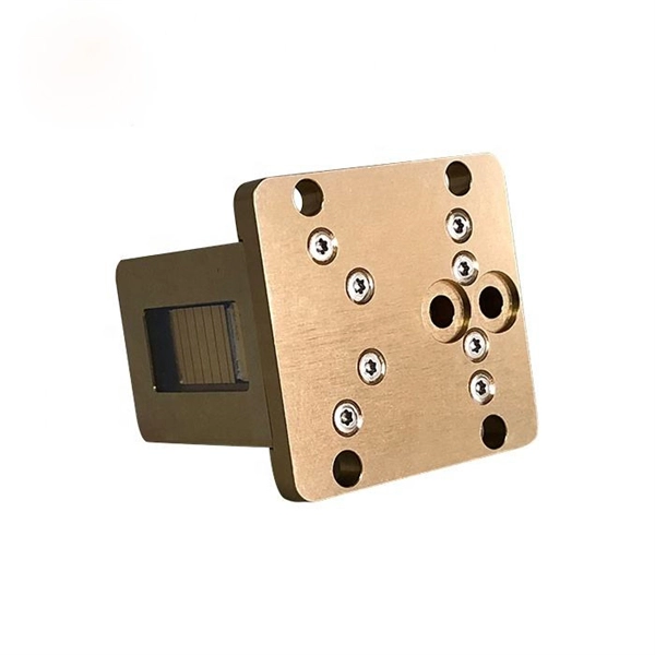
As pluggable I/O data rates increase, the need to efectively limit EMI emissions and heat generated by fiber optic transceivers simultaneously arises. Typically this is done through an EMI containment vehicle such as a sheet metal cage or die cast housing. Legal status (The legal status is an assumption and is not a legal conclusion. Google has not performed a legal analysis and makes no representation as to the accuracy of the status listed. ) Current Assignee (The listed assignees may be inaccurate. In this guide, we will cover everything from what causes heat, to monitoring your SFP module temperatures in real. The developments introduced in the optical communication systems have been focused in 3 main objectives: increase of the propagation distance, increase of the transmission capacity (bitrate) and reduction of the deployment and operation costs. The achievement of these objectives was only possible. With the growing global deployment of Fiber-to-the-Home (FTTH) networks driven by the demand for ensuring high-capacity broadband services, mobile network operators (MNOs) face challenges of excessive energy consumption (EC) of wired optical access networks (OANs). This article will focus on I/O. Fiber optical transceiver is one of the key components of the fiber optic communication systems. The fiber optical transceiver modules convert electrical signal and optical signal to each other to exchange information.
[PDF]
Step-by-step cable tray and conduit installation method with safety, quality and inspection procedures as per IEEE standards. But before you lay the first tray or clamp down a single cable, you need a solid plan. This guide breaks down the process step by step. Plan the Route Before You Drill No installation should start without a plan. Mark the cable tray route based on your electrical cable tray design and site. This guide covers the critical steps, from selecting the right electrical cable tray and performing accurate cable fill calculations to managing a safe cable pull through and ensuring all bonding and grounding requirements are met. For licensed electricians, mastering these principles is essential. This method statement describes a detailed procedure for properly installing cable trays and conduits for the Feeder System. The objective is to ensure safety, quality and compliance during the. Below is the detailed cable tray installation method statement not only for cable tray but also applicable for GI ladder and trunking for indoor and outdoor applications and in service rooms like pump rooms, electrical rooms and plant rooms etc. The Cable Tray system is installed in electrical rooms, plant rooms, and service corridors. The key requirements for cable tray installation include: Incorrect installation can lead to overheating, cable damage, or system failure. This is why proper planning and execution are.
[PDF]

Common methods of protecting busbars include overcurrent-based interlocking schemes, overcurrent-based differential protection, high-impedance differential protection, and percentage differential protection. Interlocking and overcurrent differential protection can be implemented with any suitable. DEFINITIONS. IV EXECUTIVE. Busbar Differential Protection Definition: Busbar differential protection is a scheme that quickly isolates faults by comparing currents entering and leaving the busbar using Kirchoff's current law. Current Differential Protection: This protection method connects CT secondaries in parallel and. Busbars play an important role in power transmission and distribution. They are employed as a central distribution point for all feeders. The problem is that the busbars. Busbars have typically been left without dedicated protection, from the following reasons: It is a fact that the risk of a short circuit happening on modern metal clad equipment is insignificant, but it cannot be completely dismissed. Nevertheless, the damage resulting from one short circuit may be. 25 kV insulation is required. These heat-shrinkable tubes for straight and bent busbars are extremely flexible, allowing them to be easily positioned on busbars and quickly instal ed using a gas torch or oven. They have a high expan-sion ratio, so each size of tubing fits a range of busbar sizes.
[PDF]

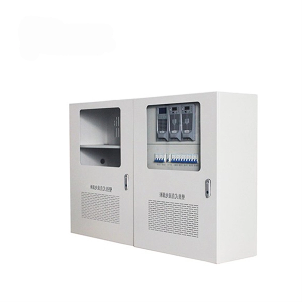
It's called a breaker box, and even though it might not look very exciting on the outside, what's behind that little door is the heart of your home's electrical system. Bottom Line Up Front: Your home's distribution box (electrical panel) is typically located in the basement, garage, utility room, or mounted outside near your electrical meter. To find it quickly, look for a rectangular gray metal box about the size of a medicine cabinet, often positioned close to. Electrical panel boxes, aka breaker boxes, can be on a wall in an out-of-the-way area of your home. You can find electric panels inside cabinets, behind refrigerators, or inside clothes closets in older homes. Current National Electrical Codes (NEC) allow none of these locations. Electrical panels. The electrical panel is the central hub that distributes electricity throughout the house. Knowing where to find your electrical panel in your home helps in case of emergencies and routine maintenance. Panels are commonly found in garages, basements, utility rooms, and outdoor walls. Understanding how your electrical panel works can help you troubleshoot issues, perform basic maintenance, and know when to. When something electrical goes wrong in your home—like a tripped circuit or sudden power outage in one part of the house—most people instinctively head to that gray metal panel, often hidden in a basement, utility closet, or garage. Having the breaker box.
[PDF]

from outside the US. EMEA Specific: +49 (0) 228 7489 201 HCS and GiHCS are registered tradema time without notice. This document is for informational purposes only and is not intended to modify or supplement any OFS warranties or specifications relating to any of its. from outside the US. STFOC uses our patented cable jacket construction designed to protect the fiber in the harsh subsea environment. Non-KinkTMSTFOC has a patented design to protect. CommScope bundles hybrid cabling to your custom specifications, using our high-performance fiber-optic, unshielded twisted pair and coaxial cables. Devices deployed at the network edge—a 5G radio, a security camera, or an industrial sensor—require high-speed data connectivity and power. It is technically possible to have a separate fiber and electrical cable, but it adds complexity, cost, and maintenance overhead. Optical hybrid cables address. challenge—OCC has what you need. Our team will make sure the configuration is tailored to your needs and will provide a detailed quote. Email us using the Request a Quote below, or give our team a call. Drive, Avon, CT 0600 erat ing Bend Radiu erat ing Bend Radius Cons from outside the US. Teledyne ODI ofers a comprehensive line of fiber optic and electro/optic hybrid wet mate interconnect products. Wet mate connectors are available in ROV Mate, Stab Mate and Manual Mate configurati sm.
[PDF]

The use of locking cabinets with advanced steel and tamper-resistant designs utilizes physical barriers to limit access to sensitive materials, making them harder to reach for unauthorized individuals. This pressure can cause the gap below server cabinets, which is often 2” or more, to become an air stream between hot and cold aisles. The resulting mix of air reduces the effectiveness of a containment solution. The Cool Shield Magnetic Cabinet Skirt provides an easy fix for this issue. These. Commercial environments have evolved as technology advances, and having a robust cabling infrastructure is crucial for scalability, minimising downtime, and enhancing productivity. Educational institutions are increasingly adopting smart technologies and cloud-based resources, so the foundation of. Many network devices are stored in the cabinets. In order to meet the normal operation of these devices in the cabinets, when the computer room cabinets are full of various cabinets and devices, we need to consider how to place the network cabinets? 1. Network cabinet placement skills (1) Before. A network cabinet is defined as a physically enclosed compartment built to store networking gadgets like patch panels, modems, switches, and a multitude of cables. Network cabinets support large, modular network switches by providing additional space for cable management and side-to-side airflow solutions. Networking cabinets tend to have.
[PDF]
Coherent optical module refers to a typically hot-pluggable coherent optical transceiver that uses coherent modulation (//) rather than amplitude modulation (RZ//) and is typically used in high-bandwidth data communications applications. typically have an electrical interface on the side that connects to the inside of the system and an optical interface on the side that connects to the outside world through a fiber optic cable. The technical details of coherent op.
[PDF]

This document discusses the implementation for Cisco Software-Defined Access (SD-Access) deployments for Airports. For the associated deployment guides, design guides, and white papers, refer to the following documents:. The low noise Silent Switcher architecture simplifies design and PCB layout to help streamline development and reduce the chance of a redesign. The compact Silent Switcher solution size supports a range of applications, including industrial, instrumentation and measurement, healthcare, aerospace. AIRPORT ELECTRICAL DESIGN STANDARDS Los Angeles World Airports 1. 1 GOALS The goal of this section is to provide guidance for all electrical work at LAWA. Additional discipline specific guidance related to electrical work can be found throughout the Design & Construction Handbook (DCH). This page provides a quick reference to engineering, design, and construction standards for various airport-related equipment, facilities, and structures. Visit our Series 150 Advisory Circular Library for a complete listing of current advisory circulars. Simpleway's battle-tested hardware ecosystem combines nnounce audio devices with digital signage controllers, creating a unified communication infrastructure built from real airport experience - from routine gate operations to full-terminal evacuations. Discover how nnounce devices create a.
[PDF]
