
Where traditional computer chips push electrons through copper wires, silicon photonic chips guide photons (particles of light) through tiny channels called waveguides etched into the same silicon material. The result is faster data transfer, less heat, and dramatically lower. Silicon photonics is a technology that uses light instead of electrical signals to move data through circuits built on silicon chips. The silicon is usually patterned with sub-micrometre precision, into microphotonic components. These operate in the infrared, most commonly at the 1. More simply, while traditional semiconductors like CPUs, GPUs, and SoCs in computers and smartphones are silicon-based integrated circuits, silicon. Silicon photonics is a type of integrated photonics that utilizes silicon-based fabrication processes to create optical chips. Thereby it opens a route towards very advanced PICs with very high yield and low cost. More precisely, silicon photonics. Photonic crystals with extremely high quality cavities. Waveguide losses dominated by scattering. Use better litho + etch CROSSINGS. Optional undercut to lower thermal leakage. ELECTRO-OPTIC EFFECT IN SILICON: INJECTION VS.
[PDF]

A phase-sequence relay monitors phase rotation in three-phase systems, protecting equipment from damage due to incorrect or reversed phase order. It guards a 3-phase device against any potential damage due to sequence change. They are deployed anywhere with a phase-sequence change that can damage the device or circuit. They work like a conventional electric relay. The order of these voltages is typically designated as ABC, where A, B, and C represent the phases. The correct phase sequence is vital for proper functioning and protection of various. Engineers use a Phase Failure Relay, which is additionally known as a Voltage Monitoring Relay (or) a Phase Sequence Relay to avoid costly breakdowns. This small but powerful equipment continuously monitors the state of the three-phase supply & guarantees that motors work only according to safe. A phase sequence relay is a tool that controls the correct sequence of phases in three-phase electrical systems. It is basically a special type of protective device that is used to monitor and control the sequence or order in which the phases of a three-phase power supply are connected. The primary function of a Phase.
[PDF]

It operates by splitting incoming light into one or two beams, with one or more beams passing through the optical element and one or more beams being redirected at an angle away from it. This tool is crucial for various applications, including lasers, heads-up displays, and other. Beamsplitters are fundamental components in optical engineering, serving to precisely divide a single input beam of light into two distinct output beams. This division allows for the simultaneous analysis or utilization of the light's properties along two separate paths. It is a crucial part of many optical experimental and measurement systems, such as interferometers, also finding widespread application in fibre optic telecommunications. In its. Beamsplitters are optical devices able to either split an incident light beam into two separate beams or combine two incoming beams from distinct angles into a single output. These versatile tools can split both laser and regular light, depending on the application in question. Image Credit: Shanghai Optics Most plate beamsplitters are. Explore the precision, applications, and design principles of beam splitters, essential for advancements in scientific research and technology. Beamsplitters are often classified according to their construction: cube or plate.
[PDF]

At its core, an overcurrent relay operates on a very simple concept: detect excessive current, then trip fast and isolate the fault. When current surpasses the relay's pickup setting, an internal mechanism triggers the circuit breaker. IEEE/IAS/I&CPSD Protection & Coordination WG Chair Jacobs Canada, Calgary, AB rasheek. com IEEE Southern Alberta Section PES/IAS Joint Chapter Technical Seminar - November 2016 Protective Relays - Technical Seminar Nov 2016 - Copyright: IEEE 2 Abstract: Protective relays and devices. Relay protection against high current was the earliest relay protection mechanism to develop. From this basic method, the graded overcurrent relay protection system, a discriminative short circuit protection, has been formulated. Types of over current relay. It is really current monitoring relay. Overcurrent Relay Definition: An overcurrent relay is a protective device that operates solely based on current without the need for a voltage coil. These relays are known for their speedy operation during a fault and are hence used widely in high-voltage applications. Let's know in. The Art and Science of Protective Relaying, by C. Mason, John Wiley and Sons, 1956. Evaluation of Distribution System Relaying Methods, by A. McConnell, Presented at the Pennsylvania Elec-tric Association, May 16-17, 1957.
[PDF]
This article presents a novel solar photovoltaic energy harvesting system for charging the high voltage Electric Vehicle (E.V.) battery using a Partial Resonant Inverter (PRI) driven doubler rectifier circuit. The.
[PDF]
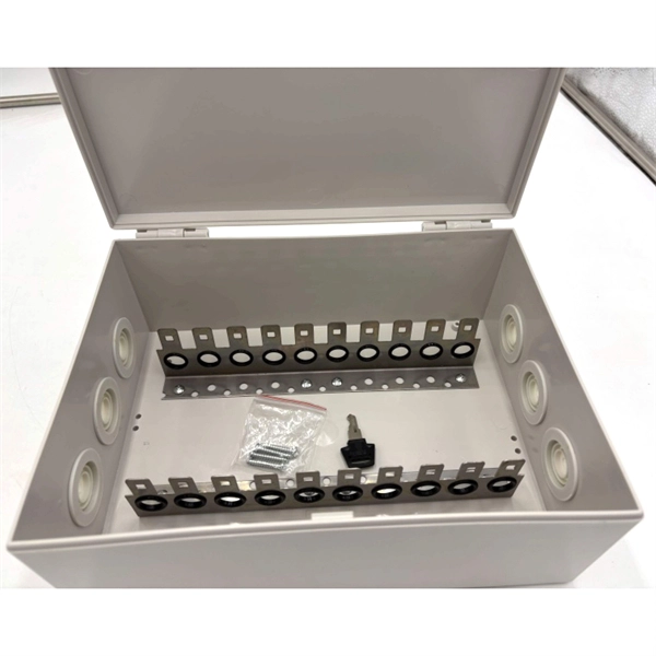
View inventory, pricing and order now for same day shipping!. View inventory, pricing and order now for same day shipping!. Check each product page for other buying options. This product has sustainability features recognized by trusted certifications. Learn more Need help? Find weatherproof electrical enclosures with stainless steel latches and hinged covers. Ideal. Polycase's IP67 rated enclosures and boxes provide protection for your electronics in indoor and outdoor applications. With a variety of sizes available in aluminum or. Box products are used to contain or enclose materials or equipment in a variety of contexts; plastic or metallic boxes suitable for constructing enclosures for electronic equipment such as guitar pedals, equipment cases for transporting tools or equipment, console style enclosures convenient for. An IP67-rated 19-inch metal enclosure rack is a high-performance housing solution designed to protect sensitive electronic and industrial equipment from dust, water immersion (up to 1 meter for 30 minutes), and harsh environmental conditions. They are perfect for use in a variety of applications, including industrial and commercial settings. Made from high-quality materials, these water-resistant enclosures offer a. Discover IP67 storage solutions with waterproof boxes and containers. Durable plastic, stackable design, and latching features for secure storage. Perfect for outdoor and rugged environments.
[PDF]

A relay protection tester is a core device used to verify the performance of relay protection devices. Its working principle can be summarized as “signal excitation – behavior detection. ”. It is divided into two parts: the main loop and the auxiliary loop. ” The tester has a built-in high-precision programmable power supply, capable of simulating various operating. When the transformer wiring type is Y/Y (Y0), the test wiring is very simple: when testing phase A, the tester IA is connected to the phase A of the high voltage side, and the tester IB is connected to the phase a of the low voltage side. After the neutral line of the high and low voltage sides is. Relay protection aids in detecting and preventing faults in electrical systems such as overcurrents or short circuits. As a core part of electric system reliability and safety, protective relays aid in preserving equipment and maintaining stability by isolating affected zones automatically via. THEY SHOULD BE GIVEN FIRST LINE MAINTENANCE ATTENTION. COMPREHENSIVE INSPECTION, MAINTENANCE AND TESTING PROGRAM. ” relay may only need to operate for 0. 15 seconds in its 30+ year life. But failure to operate as intended can result in extensive damage, extended power outages, and loss of life. NETA. Megger's smart relay testing solutions and expert support help you validate protection performance, improve system reliability, and ensure continuity of power across your network.
[PDF]
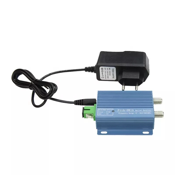
As an important part of fiber-optic communication, an optical module is a photoelectric converter which converts electrical signals into optical signals and vice versa. An optical module works at the physical layer of the OSI model and is one of the core components in the fiber. They mainly consist of optoelectronic components (such as optical transmitters and receivers), functional circuits, and optical interfaces, aiming to achieve the functionalities of optical-to-electrical and electrical-to-optical signal conversion in optical fiber communication. The working. Optical fiber consists of a cylindrical core that propagates light and a concentric cladding that surrounds it. The cladding's refractive index is slightly smaller than that of the core, which confines light within the core and propagates by repeated total reflection at the boundary with the. Broadband Circuits for Optical Fiber Communication, E. Sackinger, Wiley, 2005. Design of Integrated Circuits for Optical Communications, B. High-Speed Digital. The frequency response characterization of these electrical-to-optical (E/O, modulators sometimes integrated with lasers) and optical-to-electrical (O/E, photo detectors and receivers) converters can be important in terms of such parameters as bandwidth, flatness, phase linearity and group delay.
[PDF]

This occurs because when s-polarized light hits the reflecting surface, the electric field is in the same plane as the surface. The set up is either: Camera lens - beam splitter - camera x2 Or, Beam splitter - (lens + camera) x2 I want to be able to take 2x photos at once, so the light has to go through the beam splitter. I used the polarised flexible sheet as a proof on concept, which worked but need to make it more. A beam splitter or beamsplitter is an optical device that splits a beam of light into a transmitted and a reflected beam. It is a crucial part of many optical experimental and measurement systems, such as interferometers, also finding widespread application in fibre optic telecommunications. Additionally, beamsplitters can be used in reverse to combine two different beams into a single one. The resulting beams are directed along different paths, allowing a single light. 📦 For purchasing, use the RP Photonics Buyer's Guide for beam splitters. It provides an expert-curated supplier directory, buyer-focused technical background information, and structured selection criteria to support professional procurement decisions. What are Beam Splitters? A beam splitter (or. am Splitters/Combiners. This document describes this product line, as well as general operation guidel into two output beams t beams of equal power. The standard product is designed for use in the visible spectrum 400-700 nm wavelength). The cube can only be effectively used as a splitter; used.
[PDF]

Optical attenuators use several principles in order to accomplish the desired power reduction. The types of attenuators generally used are fixed, stepwise variable, and. An optical attenuator is a passive device that is used to reduce the power level of an optical signal. The attenuator circuit will allow a known source of power to be reduced by a predetermined factor, which is usually expressed as decibels. Key requirements include minimal effect on the beam profile, low wavelength and polarization dependence, and sufficient power handling capability. The basic types of optical attenuators are fixed, step-wise variable, and continuously variable. Since too much light may saturate the fiber optic receiver, optical attenuators are often deployed in the system to reduce the light power and achieve the best fiber. An attenuator is a device designed to reduce the intensity of electrical and electromagnetic oscillations smoothly, stepwise, or at a fixed rate. It primarily ensures the power or amplitude of a signal is lowered without significantly distorting its waveform. Attenuators are extensively used across.
[PDF]

The core function of any distribution board is to allow individual circuits to draw power from correctly rated circuit breakers and for those circuits to be isolated without causing a disruption to the rest of the supply. With the continuous improvement of people's living standards, the requirements for electrical equipment are higher and higher, and the functions are more and more complete. But now the traditional distribution mode is still used in the distribution box of building users, and the single control is. kage protection units used to distribute electrical power to numerous individual circuits or consumer points. The board typically has a single incomi g power source and includes a main circuit breaker and a residual current or earth leakage protection device. Failure to strictly adhere to the warnings and cautions as well as the installation instructions may result in serious personal. These innovations improve system reliability, safety, and operational efficiency by enabling real-time monitoring, predictive maintenance, and remote control. Background Traditional distribution boxes are difficult to implement remote monitoring due to. Electric distribution companies have tens of thousands of transformation centers that perform the function of distributing electric power, taking meter readings from supply points, and that are responsible for maintaining and ensuring all the elements involved operate correctly. In order to fulfill.
[PDF]
