Check the electrical load and ensure that the sensors do not exceed the 10 Amp maximum. Check each wire for damage that may lead to a short. Replace any damaged cables. Check the tightness of electrical connections along the. Distribution boxes are the unsung heroes of our electrical systems, quietly managing power until something goes wrong. When they start tripping, overheating, or making strange noises, it's more than just an inconvenience - it's your home's cry for help. In this guide, we'll walk through these. The good news is that most issues are easy to troubleshoot, especially if you follow the steps below. Test the Circuit When devices in your new box don't work, you start by testing the circuit. You will want a voltage tester (doesn't need to be a voltmeter) for this job. The very cheapest one you. When it comes to electrical work, the small details inside a junction box can make a big difference in safety and performance. Even experienced DIYers sometimes make simple wiring mistakes that can lead to tripped breakers, poor connections, or potential fire hazards. However, in actual applications, distribution boxes often encounter a series of problems, which not. A clear troubleshooting process ensures power flows safely and efficiently. In this guide, you will learn how distribution systems work, common problems, and practical ways to diagnose issues. Electrical energy distribution refers to how electricity moves from the main supply to different parts of.
[PDF]

No, TP-Link does not directly provide fiber optic internet service to homes or businesses. The TL-SG1428PE is fully compatible with PoE devices, such as IP cameras, access points, and IP phones. Compliance with the 802. 3af/at PoE+ standard supports up to 30 W on each PoE port. Instead, TP-Link offers a wide range of networking equipment designed to work seamlessly with fiber optic internet connections that you get from your Internet Service Provider ISP. Think of them as the. Both of the TP-Link switches have SFP ports which can be used to connect to other SFP devices such as other network switches. The nice thing about using these ports is that you do not have to use up any of your Ethernet connections. Default port rate: 10G/2. To connect. My main requirements for a new home lab switch were passively cooled and fully managed devices that include features such as a full CLI, jumbo frame support, SNMPv3, sFlow, LLDP, and static routing. I originally began looking at Ubiquiti Unifi 8-port Aggregation (USW-Aggregation) switches for $269.
[PDF]

This guide will explain their functions, discuss the role of single-mode LC connectors in modern fiber optic systems, and present the logic for their adoption on a broader scale. Proper connection of fiber optic cables is essential to harness these benefits fully, as even minor errors can lead to significant performance issues like signal loss. This article will guide you through the necessary tools, materials, and methods on how to connect fiber optic cables effectively. Fiber optic internet delivers blazing-fast speeds and reliable connectivity, making it a top choice for modern homes and businesses. In this guide, we'll walk you through how to. In this article, we'll explain how to connect multiple Ethernet switches using fiber optic cables and the equipment required for this to work. Network topology refers to the way in which the links and nodes of a network are arranged in relation to each other. There are also fiber-to-fiber versions that translate between different fiber types, wavelengths, or distances. Common families support 10/100/1000 Ethernet and. This is where single-mode fiber optics comes in. Single-mode fiber is being viewed as the backbone of enterprise connections, and it is used to facilitate all 400G solutions and real-time AI solutions/applications, due to its ability to transmit data over long distances with minimal signal loss.
[PDF]
FC used throughout all applications for Fibre Channel infrastructure and devices, including edge and ISL interconnects. Each speed maintains backward compatibility at least two previous generations (I.e., 32GFC backward compatible to 16GFC and 8GFC)OverviewFibre Channel (FC) is a high-speed data transfer protocol providing in-order, lossless delivery of raw block data. Fibre Channel is primarily used to connect to in (SAN) in co. When the technology was originally devised, it ran over optical fiber cables only and, as such, was called "Fiber Channel". Later, the ability to run over copper cabling was added to the specification. In order to avoid confu.
[PDF]

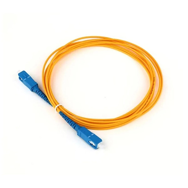
Of the more than a dozen types of fibre-optic connectors available, the four most commonly used today are LC, SC, FC, and ST. Fiber connector types LC, SC, FC, ST, MTP, and MPO are widely used in past and present. What are the differences between them? Who is the most popular one? Find the answer in the article. What is a Fiber Connector? The optical fiber connector is a kind of detachable passive optical component used. Fiber optic connectors are the unsung heroes of modern networking. They are small, often overlooked components, yet they are essential for ensuring high-speed, low-loss, and reliable optical transmission. In addition to serving the same general function, the four connectors differ in size, locking mechanism, and best applications. The following guide systematically describes. Choosing the right connector for an optical link is one of those small decisions that has outsized effects on installation density, reliability, and long-term maintenance. broadband connection is available everywhere. Its. Optical fiber terminations are the mechanical and optical interfaces that connect fiber cables to equipment, patch panels, and network hardware. They directly affect insertion loss, return loss, reliability, and long-term network stability. In this guide, we break down the most common optical fiber.
[PDF]
The term host bus adapter (HBA) may be used to refer to a interface card. In this case, it allows devices in a Fibre Channel to communicate data between each other – it may connect a server to a switch or storage device, connect multiple storage systems, or connect multiple servers. Fibre Channel HBAs are available for, computer architectures, and buses, i.
[PDF]

As a key parameter for evaluating data transmission accuracy, the bit error rate directly determines the reliability and stability of communication systems. This article delves into the fundamentals and testing methods of the bit error rate. A bit error occurs when a single binary digit is flipped during transmission, meaning a logical '0' is mistakenly interpreted as a '1' by the receiver, or a '1' is read as a '0'. Through the interpretation of actual test reports, it. BER is calculated by comparing the transmitted sequence of bits to the received bits and then counting the number of errors. The ratio of how many bits received in error over the total number of bits received is the BER. This ratio is affected by many factors including: signal to noise, distortion. Bit Error Rate (BER) is a crucial metric in signal processing and communication systems, measuring the frequency of errors in data transmission. It is defined as the ratio of the number of bits received in error to the total number of bits transmitted over a communication channel during a specified. In the fast-paced world of digital communication—where billions of bits travel through wires, fibres and wireless links every second—the concept of bit error rate (BER) is both fundamental and profound. It involves measuring the rate at which errors occur in a transmitted bitstream compared to the expected bitstream at the receiver end. The BER measurement helps in assessing the quality.
[PDF]

This article provides a comprehensive guide on how to capture network packets on a switched network using Wireshark, covering key concepts such as port mirroring, network tapping, and other methods to ensure you can monitor traffic effectively on a switched network. Packet capture is supported on the Cisco Catalyst 9300 Series Switches. The following sections provide information about the prerequisites for configuring packet capture. Before starting a Wireshark capture process, ensure that CPU. Embedded Packet Capture (EPC) is an embedded system management tool used for tracking and troubleshooting network packets. This tool helps network administrators capture packets entering and leaving Cisco devices. EPC can be used with Access Control Lists (ACLs) to filter specific packets based on. Packet capture and packet analysis are made possible by the multi-step packet capture protocol (PCAP), which makes use of many tools. Packet sniffers are tools used to do packet capture; they are the first step in the process. They are. Of course switches work on an entirely different principle and do not replicate unicast packets out of every port on the switch, but keep them isolated unless it's a broadcast or multicast. In traditional hub-based. This enables us to easily take captures directly from the switch and export them for analysis. The process is very straightforward and only takes a couple of minutes to set it up. The packets are then stored.
[PDF]

This guide will walk you through the most common fiber connector types, explaining their characteristics, advantages, and typical use cases. An optical fiber connector is a device used to link optical fibers, facilitating the efficient transmission of light signals. An optical fiber connector enables quicker connection and disconnection than splicing. Whether you're planning an FTTH deployment, upgrading a data center, or working in telecom infrastructure, this guide will help you make informed decisions. This guide provides a fully updated and industry-ready overview of LC fiber optics, explaining the origin and design of LC connectors, their key features, and the complete ecosystem of LC-based products used in modern networking. It covers LC connectors, LC patch cables, uniboot designs, armored. Fiber connector types LC, SC, FC, ST, MTP, and MPO are widely used in past and present. What are the differences between them? Who is the most popular one? Find the answer in the article. What is a Fiber Connector? The optical fiber connector is a kind of detachable passive optical component used. The answer often lies in tiny but mighty components called LC connectors. There have been many types of connectors developed for fiber cable. Single mode networks have used FC or SC.
[PDF]

The FC/PC (Physical Contact) and FC/APC (Angled Physical Contact) fiber optic connectors are standardized under TIA EIA/TIA-604-4 and IEC 61754-13. ABSTRACT: This standard describes the point-to-point physical interface portions of Fibre Channel serial electrical and optical link variants that support the higher level Fibre Channel protocols includ-ing FC-FS, HIPPI, IPI, SCSI and others. This standard is recommended for new implementations but. Fiber connector types LC, SC, FC, ST, MTP, and MPO are widely used in past and present. What are the differences between them? Who is the most popular one? Find the answer in the article. What is a Fiber Connector? The optical fiber connector is a kind of detachable passive optical component used. An optical fiber connector is a device used to link optical fibers, facilitating the efficient transmission of light signals. An optical fiber connector enables quicker connection and disconnection than splicing. Unlike fiber splicing, which is permanent, connectors allow for easy connection and disconnection of cables, making them ideal for maintenance and flexibility in. Understanding fiber connector types—SC/APC, SC/PC, LC/UPC, LC/APC, ST/PC, FC/PC, and FC/APC—is essential for selecting the right interface for your application. Each type varies by shape, polish (APC, PC, or UPC), and return loss performance, which affect PC, UPC, and APC Polish Styles: What's the.
[PDF]