Light sources are devices that generate the optical signals transmitted through fiber optic cables. In fiber communication, the most commonly used light sources are LEDs (Light Emitting Diodes) and laser diodes. LEDs are used in short-distance, low-speed systems due to their broader spectral width. Optical fiber primarily uses infrared light, not visible light, due to lower signal attenuation. Common wavelengths are 1310nm and 1550nm, where silica glass fiber has minimal loss (as low as 0. Lasers or LEDs generate the light, which carries data through total internal reflection within. Most systems use a "transceiver" which includes both transmission and receiver in a single module. The transmitter takes an electrical input and converts it to an optical output from a laser diode or LED. It often uses glass or plastic cables, which address the problems of traditional copper cables' poor speed and limited distance bandwidth carrying. VCSEL (Vertical Cavity Surface Emitting Laser)- VCSELs (pronounced 'vixel') emerged in the 80's as a new kind of semi-conductor laser and were soon recognized for their potential in fiber optics. When Gigabit Ethernet products were developed LEDs could not modulate (turn on and off) at required.
[PDF]

This comprehensive guide will delve into the most effective practices, key considerations, and strategic approaches for designing and implementing an efficient cabling system within a data center environment. At the core of data center connectivity are fiber optic cables, which are thin strands of plastic that transmit data using light signals or wavelengths, offering unparalleled speed and efficiency. The data superhighway paved by fiber optics forms the backbone of modern data centers, ensuring rapid. An end-to-end cabling system is an ideal solution for data centers especially when time for traditional cable installation and termination is limited. Explore advanced configurations, testing protocols, and industry best practices. As the demand for data surges, these switches become more vital in sustaining networks that are efficient, scalable, and. As data centers continue to grow in complexity and scale, efficient fiber optic cabling is essential for maintaining high performance, reliability, and scalability. Proper planning and implementation of cabling infrastructure can significantly reduce downtime, improve airflow, and ensure. center hardware layout design. This map should include the cabinet placements, patch panels, hardware, port-counts, trunking locations and power access connection points. Future plans for change will be discussed, as well as the bandwidth required. infrastructure design. The design's intent is to.
[PDF]
Just connect an Ethernet cable from the modem or ONT to the closest Ethernet jack, and then do the same with the router in the room where you want it (if an Ethernet jack is available, that is). The network switch connecting all your Ethernet cables should automatically pair. The process to connect fiber optic cable to router requires careful attention to detail, but I'll walk you through every critical step with the precision and clarity you deserve. This comprehensive guide combines industry standards with field-tested practices to ensure you achieve a rock-solid. Setting up an internet connection involves a complex journey, starting at the data centers where internet services are routed, and ending at subscribers' home routers. This process involves multiple fiber optic components, accessories, and networking equipment to ensure fast, reliable, and secure. However, setting up a fiber optic connection to your router can seem daunting if you're unfamiliar with the process. In this guide, we'll walk you through how to connect a fiber optic cable to a router safely and efficiently. The fiber. The primary advantage of using a wireless solution for connecting your upstairs floor to your network is that it may not require drilling holes. The simplest way to extend a Wi-Fi network is via a Wi-Fi repeater (range extender). Check compatibility: Before you begin, make sure your router supports fiber optic connection.
[PDF]

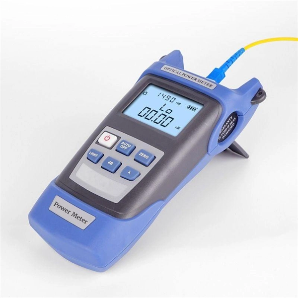
Specialized Products offers LED and laser fiber optic light sources from AFL, EXFO, VIAVI, Photonix, Tempo Communications and other leading brands. Our selection includes multimode, single mode and quad light sources, with FC, LC, SC, ST connectors and. The state, throughput, and identification of an optical fiber can be easily checked with fiber testers by coupling highly visible laser light into the optical fiber. The red light of a laser is coupled into the core of an optical fiber in a targeted manner (an LED is usually too weak a source to be. Definition: delivery of power for electronic devices via light in an optical fiber which is converted to electricity Alternative terms: power-over-fiber, photonic power Category: fiber optics and waveguides Related: fibers fiber cables laser diodes fiber optics Page views in 12 months: 3730 DOI:. Prizmatix Silver-LED fiber-coupled LEDs provide high power continuous (CW) low noise output as well as fast pulsed operation from optical fiber. Silver-LEDs are available at deep UV, UV, Violet, Blue, Green, Yellow, Red or NIR. Fiber Coupled LED light source modules are ideal for use with high NA. This paper discusses the application of fibre optic technology and its benefits in the operation of solar power plant. Fibre optic technology enhances solar power plant operations, ensuring reliable data transmission and control.
[PDF]
This is the power of fiber optic sensing, a technology that transforms ordinary optical fibers into the digital world's sensory network. In 2023, researchers turned submarine cables into earthquake warning systems and gave electric vehicles “optical nerves” to prevent battery failures. We create the most compelling fiber optic sensing solutions, empowering the world to optimize assets, protect lives and the environment. From expert consultation to seamless integration and long-term support, our services ensure the success of your fiber optic sensing solution. Fiber optic sensing works by measuring changes in the “backscattering” of light occurring in an optical fiber when the fiber encounters vibration. Optical fiber sensing technology makes it possible to detect and predict physical events and activities across the globe. By combining. Large 3C seismic vector sensor arrays using fiber optic accelerometer technologies for deployment in the harshest of conditions in vertical, deviated and horizontal wells. We offer the most extensive line of fiber stretchers and interferometers available in today's market for interferometric. FEBUS Optics is the world reference in DFOS, distributed fiber optic sensing systems (DAS, DTS and DSS), to reduce the environmental impact of human activity, protect people, and optimize production. FEBUS provides state-of-the-art devices and turnkey solutions based on its patented technologies.
[PDF]
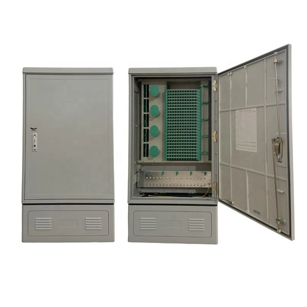
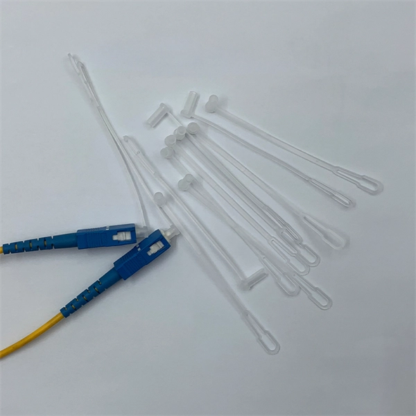
This cabling system organizes and manages fiber optic cables and copper cables through cable trays, patch panels, and structured cabling systems, enabling easy maintenance and scalability. Fiber and Cat6a can run together in shared trays when properly separated. Protect the fiber bend radius at all transition points. Avoid stacking heavy copper bundles on delicate fiber. Separate power cables from data cabling. Prevent tray overcrowding to maintain airflow. Wire mesh trays enhance. Data center cabling refers to the organized system of cables and related infrastructure to connect and manage the various components within a data center. This system ensures efficient data transmission and reliable connectivity in a data center environment. Structured cabling is a methodical. As data centers continue to grow in complexity and scale, efficient fiber optic cabling is essential for maintaining high performance, reliability, and scalability. Cabling not only supports current performance but also ensures future adaptability. Proper planning and implementation of cabling infrastructure can significantly reduce downtime, improve airflow, and ensure.
[PDF]

Also, please take a look at the list of 18 fiber optic sensor manufacturers and their company rankings. Omega Engineering, Inc. What Is a Fiber Optic Sensor?. The top companies in distributed fiber optic sensors market are shaping a rapidly evolving ecosystem driven by infrastructure digitization, energy transition, and advanced monitoring requirements across critical industries. The market is estimated to exceed USD 2. Their systems offer a compelling combination of advanced technology (often utilizing Brillouin or Rayleigh scattering). Fiber optic sensor companies manufacture sensors that use optical fibers for detecting changes in physical properties like temperature, pressure, and strain. The technology is developed at the VU in Amsterdam they built several applications based on the technology, for both academic as well as. com/ Echopoint Medical is a. Fiber optic shape sensing platforms delivering full-length device awareness for radiation-free navigation and real-time procedural insight What is Shape Sensing? Fiber optic shape sensing uses embedded sensors to measure the full 3D shape of a flexible surgical device along its entire length in.
[PDF]

When it comes to testing fiber optic cables, a Visual Fault Locator (VFL) is an essential tool in your toolkit. A VFL is used to detect faults, breaks, or bends in fiber optic cables by emitting a bright red light that is visible even through the fiber's jacket. It's a cost-effective and. A Visual Fault Locator which can be also called visual fault identifier (VFI), fiber fault locator, fiber fault detector, etc., is a visible red laser light designed to inject visible red light energy into an optical fiber. Using a VFL to diagnose issues can save time and cost when diagnosing an. A visual fault locator is a compact, handheld device that emits a visible light beam, typically in the red wavelength range, through a fiber optic cable. It works by injecting a visible red laser light into the fiber, which can be seen through the jacket or at the end of the cable. If the light doesn't come out the other side, there might be a problem. You. And in the end we will show you how to use an old cell phone's camera to detect light in a fiber optic system. It uses a bright incandescent bulb or visible LED source to.
[PDF]

If the LOS light on your fiber router or ONT is blinking red, it usually means Loss Of Signal. This guide explains the likely causes, the checks you can do at home, and when the issue needs technician support. The LOS light on your router indicates the status of your internet connection to the Internet Service Provider (ISP). When it's green and steady, everything is fine. However, when it blinks red or stays solid red, it signifies a Loss of Signal, a problem preventing your router from communicating. Troubleshoot your router's red light with these steps. You might feel like you're staring into the abyss of digital darkness, wondering what went wrong. But don't despair! This guide will walk you through the most common causes of router. The tables in this article provide detailed information about the possible appearances of the LED lights on each device, the possible causes of each state, and what you should do. Existing Krishii Fiber customers can share their registered mobile number, area and a. Experiencing a solid red broadband light on your router can be frustrating and indicates a disruption in your internet connection. Understanding the possible causes and fixes for this issue is crucial to getting your connection back on track. We will explore common reasons behind the solid red.
[PDF]

An optical module sends data as light through fiber cables. Light is faster than electricity, making it great for quick communication. The optical module serves as a crucial component in optical fiber communication systems, operating at the physical layer, which is the lowest layer in the OSI model. Its primary function is to achieve optoelectronic conversion by converting electrical signals into optical signals and vice versa. This technology is crucial for fast and reliable data transfer in networks. Optical modules typically have an electrical interface on the side that connects to the inside of the system and an optical interface on the side that connects to the outside. Optical fiber transmission forms the backbone of modern high-speed communication networks, enabling the efficient transfer of massive datasets across vast distances. These modules typically consist of a transmitter, which converts electrical signals into a light signal, and a receiver, which converts the received signal back. In high-speed data networks, the seamless integration of fiber optic cables with SFP (Small Form-Factor Pluggable) modules is critical for reliable signal transmission. SFP transceivers bridge electrical and optical signals, making them indispensable in data centers, telecom networks, and.
[PDF]
High-definition temperature sensing based on the natural Rayleigh backscatter in optical fiber delivers a virtually continuous line of temperature measurements with sub-millimeter spatial resolution. 1. Map temperat.
[PDF]
Protect border security against illegal crossings, smuggling and unauthorized intrusions with a 24/7, real-time fiber optic perimeter intrusion detection system (PIDS) that can be mounted on fences, buried underground or deployed in a top-of-wall configuration. AP Sensing's Distributed Acoustic Sensing (DAS) technology delivers real-time perimeter and border protection by transforming standard optical fibers into dense acoustic sensor arrays. Acting as a Perimeter Intrusion Detection System (PIDS), DAS provides continuous, highly precise monitoring. It. The basic idea of fiber sensing technology is to utilize optical fibers as distributed optical sensors to detect and monitor changes in temperature and strain in a fiber or detect vibrations (sound/acoustics) in the environment around a fiber. It can also be used to protect data conduits and buried pipelines. Advanced adaptive signal processing along with certified SMS/VMS integration options ensure the. Perimeter Intrusion Detection Systems are systems used in an external environment to detect the presence of an intruder attempting to breach a perimeter. Modern security systems, driven by. Technica Fiber Tech's Fence Rakshak is a Fiber Optic based Perimeter Intrusion Detection System (PIDS) that can make organisations fully secure by identifying intruders and blocking such access. Our turnkey solutions can identify any unauthorized intrusions, evaluate the situation, and track.
[PDF]

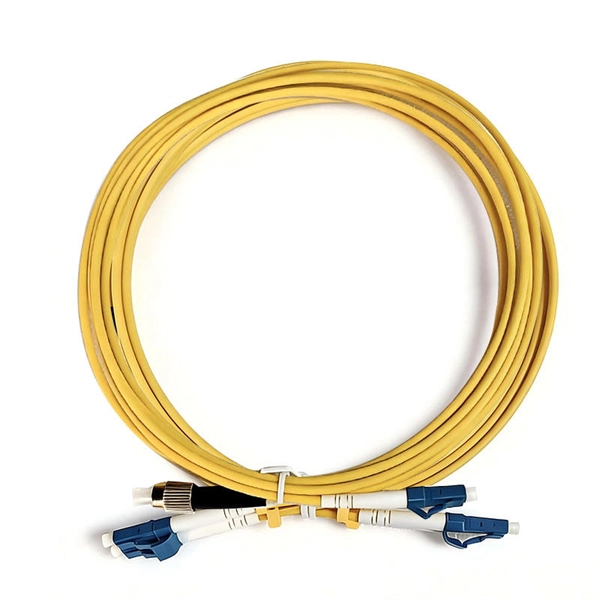
Fiber-optic communication is a form of optical communication for transmitting information from one place to another by sending pulses of infrared or visible light through an optical fiber. The light is a form of carrier wave that is modulated to carry information. Fiber is preferred. This method encodes data into light signals by modulating properties like wavelength, phase, and polarization. The light signals propagate to the receiver through the fiber optic cable. Optical fiber communication relies on the properties of light from the electromagnetic spectrum. By optimizing. These strands, known as fibre optic cables, have revolutionised telecommunications because they transmit information using pulses of light. Unlike copper wires, which send electrical signals and suffer from resistance and interference, fibre optics offer orders of magnitude more bandwidth and. Optical Fiber Light Transmission commonly known as fiber optics is a technology that utilizes thin transparent fibers made of glass or plastic to transmit data and information using the light signals. This technology forms the backbone of global data transfer due to the immense bandwidth capacity of light. Light waves possess a frequency spectrum vastly wider than. Less costly per meter. Lower transmitter launching power. Less susceptible to electromagnetic interference. Flexible use in mechanical and medical imaging systems. Automotive and many other industories.
[PDF]