
The Tellabs FlexSym® Optical Line Terminal One (OLT1) provides a small form-factor OLT supporting both GPON and XGS-PON in the same OLT. Explore our range of high-quality GPON, EPON, and XG (S)PON OLT products. Find the perfect Optical Line Terminal solutions for your network needs. At the heart of a point-to-multi-point or passive optical network (PON) is the optical line terminal (OLT). Modern OLTs offer communication service providers (CSP) the ability to launch multigigabit services to tens of thousands of subscribers from a single location or just ten. It provides flexible choices for designing a modern enterprise network to exactly align with contemporary connectivity. Zyxel's GPON OLTs offer advanced signal processing for dense deployments. Upgrade to gigabit symmetric services today and prepare for tomorrow's technologies. Generic 19" inch ZXA10 C320 GPON OLT 2pcs of SMXA/1 (1. 25G),1pc of GTGH 16 ports with SFP, Optical Line Terminal What is Desertcart? Is it safe to order from?+ Customer service was outstanding when I had questions about the product. Great price for an authentic product. Fast international shipping. High-Performance 16-Port XGS-PON OLT with 40G/100G Uplink CapabilityPLANET XGPL-16000 is a high-density 16-Port XGS-PON Optical Line Terminal ( OLT) designed for next-generation fiber broadband access. Product overview GXR101 Pro is an integrated optical access node combining ONU, OLT.
[PDF]
An optical line termination (OLT), also called an optical line terminal, is a device which serves as the service provider endpoint of a passive optical network. It provides two main functions: to perform conversion between the electrical signals used by the service provider's equipment and the fiber optic signals used by the passive optical network.to coordinate the multiplexing between the conversion. FeaturesOLTs include the following features: • A downstream frame processing means for receiving and churning an cell to generate a downstream frame, and converting a parallel dat. Most vendors integrate an entire fiber optic management system for ISPs to manage OLTs as well as client ONTs and as such are not interoperable. • • BT-PON.
[PDF]

Explore the comprehensive cost analysis of Optical Line Terminal (OLT) technology, including benefits, features, and long-term value for network operators and service providers. OLT (Optical Line Terminal) cost represents a significant consideration in fiber optic network deployments. An OLT serves as the endpoint hardware in a passive optical network (PON), managing the conversion between electrical and optical signals. With superior performance and reliability, it suits large-scale enterprise infrastructures and service providers. It's ideal for high-speed data transmission and long-haul applications. Pier is a compact, powerful connectivity device for enabling fiber-to-the-x (FTTx) broadband services across extended distances. OLT chassis are the physical enclosures that hold all of the OLT components, such as circuit boards and power supplies, ensuring that everything is securely housed and organized. OLT. Explore our range of high-quality GPON, EPON, and XG (S)PON OLT products. It provides two main functions: to perform conversion between the electrical signals used by the service provider's equipment and the.
[PDF]

Strip the cable the required length, minimum 0. 5 meter or more, to establish easy and safe installation with enough buffer size. Pass the stripped cable into the upper side of the splice tray. Fix the cable strength member (3) on part (2) and stabilize with cable fixing part. To establish easy and safe installation put the box where it will be installed and measure the required length of the cable. 5 meter or more, to. Lockable Cable inputs: 2x 12mm - 16x Space for 1x16 SC splitter or 1x32 LC splitter 1. Cable fixing Instert the stripped cable through the cable entry port and fasten the FRP element(s) to the block. The outher coating should be fasten useing the steel hops. Do not fasten too. Stripping and preparing fibre optic cables for termination is a critical step in the installation and maintenance of fibre optic networks. Firstly, it is important to consider that when stripping multi-layer cables for connectorization, each layer must usually be stripped individually, as they all usually need to be stripped to different lengths. Cutting and stripping the cable jacket can be done with a special fiber stripper or a properly set wire stripper as long as it does. Whether it is indoor or outdoor fiber-optic (FO) cable, using a step-by-step approach reduces the chance of fiber damage while ensuring the performance of fibers. In our continuing discussion of installing FO cables, let's use a step-by-step approach in detailing how to strip and clean indoor and.
[PDF]

How to Install a Fibre Connector into a Patch Panel (Easy fibre optic connector installation) How to Install a Fibre Connector into a Fibre Optic Patch Panel. How do you install fibre optic connectors?. Connecting a fiber patch panel to a switch is a critical step in setting up a fiber optic network. There are different types of connectors. In today's high-performance networks, fiber optic patch cables are the lifelines that ensure smooth data flow across switches, servers, and routers. Even the most advanced optical transceivers can only perform at their peak when paired with properly installed, clean, and precisely managed fiber. Choose an SFP module based on the fiber optic cabling that will be connected to the network switches. SFP transceiver modules almost always require two fiber optic cable strands. A Fiber Patch cord connects two devices. You plug it into a switch, router, or patch panel. It's ready to use out of the box. A pigtail is for splicing. You fuse it to a. With a railroad switch (patch panel), the train (data) can travel from A to B, C and even more destinations, otherwise it can only go from A to B, or C to D. This article, What Is a Patch Panel Used for?, has explained it thoroughly.
[PDF]

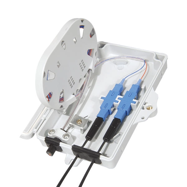
- YouTube This kind of box are used in the end termination or residential building sand villas, to fix and splice with pigtails, can be installed on the wall. Thus, a fiber termination box is used to terminate the optical fiber cables in the field and connect them to the pigtail by splicing. After an optical cable arrives at the user's end, it is fixed in the terminal box. Fiber Optic Terminal. Fiber Terminal Box is a terminal protection box for the splicing of fiber optic cable and pigtail. Fiber optic terminal box is a cable end fitting. Modern home networking often relies on a Fiber-to-the-Home (FTTH) connection, which typically terminates at a service provider's external box. Running fiber internally involves extending this high-speed link from the service entry point to a centralized location, such as a dedicated media closet or. This termination box supports 0. 0mm pigtails and 2x3mm indoor drop cables. Furthermore, this fiber termination box's innovative flip-up distribution panel simplifies installation and maintenance, allowing for easy access and efficient handling.
[PDF]
The in-service monitoring of civil infrastructures is an important task required to achieve their smart operation. This task requires the installation of sensors to continuously check and control the structures' st.
[PDF]

The optical power meter is similar to the voltohmmeter in application but measures the optical resistance (losses measured in dBm or dBM) of a cable before and after installation and provides a comparative analysis of the splices. The range of the meter is adjustable. Regularly testing fiber optic cables helps minimize network downtime, lengthens the network's longevity, reduces maintenance requirements, and helps support network reconfiguration and upgrades. These factors significantly add to the fiber optic network's long-term performance, manageability, and. Several types of tests are commonly conducted to assess and maintain the health of fiber optic networks. Continuity testing verifies that the fiber is intact and that light can pass through from one end to the other without any blockages. These test procedures assess the physical and functional qualities of fiber optic cables, connectors, and the network as a whole. Key tests include: Effective fiber testing utilizes advanced tools such as Optical. One way to test a splice is to use an Optical Power Meter. As the components like fiber, connectors, splices, LED or laser sources, detectors and receivers are being developed, testing confirms their performance specifications and helps. Regular testing of fiber optic cables is not just a preventive measure; it's an investment in the longevity and efficiency of your network. By identifying potential issues early, you can enhance.
[PDF]

The document discusses optical detectors used in fiber optic communications systems. It describes the functioning of PIN photodetectors and avalanche photodetectors (APDs). Their performance. An optital detector is a device that converts light signals into electrical signals, which can then be amplified and processed. Such detectors are one of the most important components of an optical fiber communcation system and dictate the performance of a fiber optic communication link. PIN Photodiode A PIN photodiode is a widely. Detectors perform the opposite function of light emitters. The most common detector is the semiconductor photodiode, which produces current in response to. It explains how these devices use optical fibers to measure quantities like temperature, mechanical strain, pressure, and vibrations by detecting changes in light propagating through the fiber. A central focus is on sensors based on fiber Bragg gratings, where the Bragg wavelength is sensitive to. Optical Power Meters: These devices measure the power of optical signals in fiber optic cables. This information helps in maintaining signal integrity and quality across the.
[PDF]

There are two ports on the left side of the switches reserved for functions outside of communicating with the node and storage array. The ports are labeled: the serial port used to configure the switch. The Cisco MDS 9148S switch provides the following types of ports: Console port (Interface Module)—An RS-232 port that you can use to create a local management connection. MGMT 10/100 Ethernet port (Interface Module)—An Ethernet port that you can use to access and manage the switch by IP address. A vertical line, called a pipe, indicates a choice within a set of keywords or arguments. [x | y] Optional alternative keywords are grouped in brackets and separated by vertical bars. Cisco Catalyst 9500. These are located on U28 and U27 respectively. This fiber switch utilizes OEO Technology. The Primary Remote Control is an RJ45 port that is 10/100 Base-T Ethernet and is IP addressable. Access either of two LC Duplex Fiber Optic Networks from one computer connected. The switch is typically grounded during installation and provides an ESD port to which you can connect your wrist strap. Do not remove and insert a transceiver more often than is necessary. One of the Ethernet ports can also be used to export analytic.
[PDF]
Long-haul transmission uses fiber optic cables to send data quickly and securely over long distances, connecting cities and countries for fast communication. Whether you're connecting a data center or simply linking your home office to a shop, it's important to understand the fundamental aspects of fiber optic. Long-distance fiber optic transmission is a fascinating field where physics, engineering, and innovation converge to power our digital lives. By leveraging technologies like DWDM, optical amplification, and high-performance coherent optical transceivers from industry leaders like LINK-PP, we. Fiber optic cable transmission distance is determined by two primary physical factors that affect signal quality as light travels through the fiber medium. Attenuation is the progressive loss of signal strength that occurs as light travels through the fiber. The greater the distance, the greater. Fiber optic cables have revolutionized modern communication networks by enabling blazing-fast data transmission across vast distances. However, fiber cable runs are not limitless. This exploration examines their workings, efficiency principles, and modern applications. Glossary terms are explained in the Glossary Section. A fiber optic cable can contain a varying number of glass fibers, from a few up to a couple hundred. Another glass layer called cladding surrounds the glass fiber.
[PDF]

Single-mode optical splitters are optimized for single-mode optical fiber, while multimode optical splitters are tailored for use with multimode optical fiber. An Optical Splitter, also known as a beam splitter, is a passive optical device that divides a single input optical signal into two or more output signals. Conversely, it can also combine multiple signals into one. Its primary role is in Passive Optical Networks (PON), which are the foundation of. This guide demystifies fiber optic splitters, explaining their design, operating principles, types, key specifications, and real-world applications. It can distribute the optical energy transmitted through a single fiber to two or more fibers in a predetermined ratio or combine the optical energy from multiple fibers into one fiber. “Passive” means it needs no. You use optical couplers and splitters to split or join signals in fiber networks. For example, optical splitters send light to many output ports. This lets you connect more users to one network terminal. There are different types of fiber optic splitters available, with two of the most common being Fused Biconical Tapered (FBT) splitters and Planar Lightwave.
[PDF]
The Telecoms crash, also known as the Telecommunications Bubble was a that occurred in 2001, after the bursting of the. The telecommunications industry had experienced significant growth and investment during the 1990s, fueled by the expansion of the internet and the introduction of wireless technology. Companies such as,, and had achieved enormous market valuations base.
[PDF]


