
This blog article entry considers the merits of choosing which of various low loss RF coaxial cables to use for IoT, LTE or LORA wireless applications where an external antenna is used to connect to router, gateway or terminal. The choice looks deceptively simple—pick a length, screw it on—but RF engineers know the truth: every extra meter quietly eats away at your link budget, especially once you cross 2 GHz. It's not just about length; the cable type, connector quality, and even mounting environment make a measurable. Audio generated by DropInBlog's Blog Voice AI™ may have slight pronunciation nuances. In this article, we will consider cables such as RG174, RG58, RF195. The cheap connectors have inferior dielectric between the poles as well as poorer grades of metal. The dielectric won't handle high power (KW range) as well and the center pin can more easily shift causing impedance problems if they are moved frequently. RF connectors are usually used with coaxial cables. They are designed to maintain the shielding that the coaxial design offers. The better and newer. Besides the wide range of RF connectors, Telegärtner also provides a considerable range of suitable coaxial low loss cables. Using this one-stop shopping option at Telegärtner makes your purchasing process even more efficient. The main use of low loss cables are all kinds of wireless applications.
[PDF]
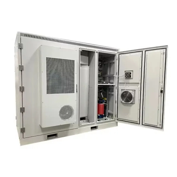
Find Prefabricated Telecom Shelter manufacturers, suppliers, dealers & latest prices from top companies in India. We are the first Indian company to provide 'Ready to Erect' Telecom Shelters in India with in-house Design, Engineering, Manufacturing and Erection / Installation capability all across India for efficient and cost effective operations of telecom equipment. (Dust Weather proof Insulated Cabin for. Prominent & Leading Manufacturer from Greater Noida, we offer portable prefabricated shelters and puf insulated telecom shelter. Our broad scope of pre-assembled covers incorporates a wide exhibit of Portable Telecom Shelters. Designed for rapid deployment and exceptional durability, our portable shelters are ideal for various applications, including the telecom and railway. Leading Manufacturer of prefabricated telecom shelters from Faridabad. Constructed with durable materials, these shelters ensure reliable performance.
[PDF]

This article provides a detailed technical comparison between fiber optic and copper cables, offering a clear perspective for engineers, network architects, and procurement managers. The core distinction between the two technologies lies in the physics of data. However, the exponential growth in data demand has positioned fiber optic technology as the superior alternative for performance, scalability, and future-readiness., 10G/25G/40G/100G and beyond depending on optics and reach). Copper Ethernet scales too, but practical limits are lower and depend. The two main options are fiber optic cables and copper cables, each with its own advantages and drawbacks. Fiber optic cables are praised for their high performance and scalability, while copper cables remain a cost-effective choice, especially for budget-conscious projects and older systems. Copper wire is more susceptible to interference and has limited data capacity, making optical fiber the preferred choice for modern high-speed. Optical connectivity, utilizing fiber-optic technology, has emerged as the superior choice for modern networking, offering unparalleled performance, reliability, and scalability. For example, a typical 10 Gbps copper Ethernet link (such as Cat 6A) over 100 meters can consume approximately 5 to 8+.
[PDF]

Compare fiber optic and copper Ethernet cables across speed, distance, cost, installation difficulty, and use case metrics. Use the interactive scenario selector to find the right medium for your specific network — all processed locally in your browser. PoE Required?. The core difference between fiber optic and copper cables lies in how they carry data. One uses light, the other electricity—and that distinction shapes everything from speed to signal integrity. Fiber optics transmit data as pulses of light through ultra-thin strands of glass or silica. Both technologies can deliver high-speed connectivity, but they behave differently under real-world constraints such as. However, the exponential growth in data demand has positioned fiber optic technology as the superior alternative for performance, scalability, and future-readiness. This article provides a detailed technical comparison between fiber optic and copper cables, offering a clear perspective for. Fiber optic tends to be the more premium solution, while copper wiring is far more common, but why is that? What are the differences between these two cable types, and why might you want to pick one over the other? Here's everything you need to know about fiber vs. copper cables, to help you pick. Several factors are converging to drive the switch from copper to fiber – and cost is a big one. A recent investor presentation by AT&T claimed that fiber was 35% less costly to maintain than copper.
[PDF]
We are importers, traders, stockists, and suppliers of a wide range of essential products and equipment for industries including Oil & Gas, Offshore, Mechanical, Marine, Water & Power, Industrial Manufacturing, Shipbuilding, and Construction across the Middle East. KTT & CO LLC was formed in 1983 for servicing the requirements of Oil, Gas & Petrochemical industries in Sultanate Of Oman. Turnover has since then crossed million dollars To represent and distribute a range of spares for mechanical, electrical and instrumentation engineering requirement of Oil &. Leading supplier of industrial equipment for Oman's oil & gas, petrochemical, and power generation sectors. Authorized distributor serving Muscat, Sohar Industrial Port, Salalah, and all Omani industrial zones. Industrial equipment for Oman oil & gas, refineries. PLCs, valves, process control for. GREENPORT SUPPLIERS is one of the OMAN's leading procurement and product supply company. Hereby we kindly request you to send us the requirement for the same in order for us to offer you the best. Our mission is to be an integral part of the Sultanate of Oman's sustainable growth and development. Through innovation, reliability, and an.
[PDF]

- Provides flexibility by offering optical and copper interconnects with the same connector system. - Enable high speed and bandwidth needed in a smaller space for next-generation ruggedised systems. Designed to unleash high-speed data center capabilities, MPO Cable Assemblies and Adapters use high-density MTP and MPO-style connectors to deliver streamlined connectivity, high port density, superior loss performance and simplified maintenance for the high-bandwidth networks of tomorrow. Data. Find a huge range of MPO Fibre Optic Adapters at Farnell Israel. We stock a wide range of Fibre Optic Adapters, such as LC Duplex, SC Simplex, LC & ST Fibre Optic Adapters from the worlds top manufacturers including: L-com, Molex & Molex / Partner Stock More Pricing. More. 1, and Telcordia GR-409 standards. - Enables. Smart Filtering As you select one or more parametric filters below, Smart Filtering will instantly disable any unselected values that would cause no results to be found. Please modify your search so that it will return results. To use the less than or greater than function, please select a value. For use in MPO Connectors & 100G-800G optical transceiver modules High optical performance, low insertion loss GR-1435-Core compliant Data center cabling & 100G-800G network solutions For high density network connections & all MPO interfaces Data center cabling & 40G/100G network solutions.
[PDF]

This article will compare waterproof connectors and non-waterproof connectors, highlighting their key differences, advantages, and best use cases in FTTH deployments. 🔍 What Are Waterproof Connectors?. In modern fiber optic deployments, one of the biggest challenges is ensuring stable and long-term connectivity in harsh outdoor environments. The comparison is typically triggered during outdoor deployments, edge network extensions, or hybrid indoor–outdoor transitions where connectors may be exposed. This is where Ruggedized Fiber Optic Connectors come in. Whether you are connecting a Remote Radio Unit (RRU) for Ericsson, Nokia, or Huawei, or setting up a harsh-environment sensing network, choosing the right waterproof interface is critical to preventing signal loss and network downtime. In. In today's fast-paced digital world, the choice of fiber optic connectors can significantly impact performance, reliability, and longevity of networking solutions. Among the varieties available on the market, waterproof fiber optic connectors have emerged as a superior option for many applications. In this blog, we will focus on comparing the performance of Mini LC.
[PDF]

In this article, we break down the major FTTx models, compare their performance and implementation contexts, and showcase how LINK-PP's high-performance optical modules support each deployment type. Huawei's fiber to the room (FTTR) solution extends fibers to rooms and provides various gigabit Wi-Fi 6 master/slave FTTR units, all-optical components, and optical cable construction tools, enabling users to enjoy stable gigabit Wi-Fi experience in every corner of rooms at every moment. In. Fibre-to-the-room (FTTR) delivers Gigabit optical capacity directly to each room in a building, providing very high-speed, reliable internet. FTTR fibre-based technology: designed to enhance digital capabilities. FTTR addresses challenges related to restricted speeds within buildings, providing. Fiber to the Room (FTTR) is a next-generation access network designed to deliver high bandwidth, low latency, and room-level optical coverage. It is envisaged that the topology and functionalities of FTTR technologies may be. Fiber to the Room (FTTR) is a possible solution to issues with indoor connectivity. Demands for high bandwidth, high bit rates in both directions, low latency, and service reliability are constantly growing. FTTR is a very effective way to improve the quality of residential broadband service and reduce customer complaints, more so with the advent of Wi-Fi 7.
[PDF]
