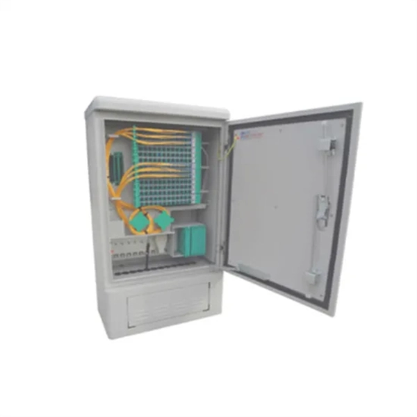
They function as junction points that manage, protect, terminate, and distribute fiber optic cables, ensuring efficient data transmission between different network elements. Fiber Distribution Boxes (FDBs) are critical components in modern telecommunications infrastructure, particularly in fiber optic networks. Whether you're a network technician, IT professional, or simply looking to understand fiber optic networks. A fiber distribution box (FDB) is a passive enclosure that provides secure splicing, termination, and distribution of optical fibers. It typically contains splice trays, adapters, and cable routing components to manage fiber connections. FDBs are used to organize incoming and outgoing cables. Discover Fiber Distribution Hubs (FDHs), fiber cabinets, and other outdoor cabinet solutions by CommScope. Efficiently manage your network with our reliable fiber optic distribution cabinet solutions.
[PDF]

In this guide, we'll walk you through the entire process of preparing fiber optic cable for splicing and termination to fiber connectors. We'll explore the necessary tools, safety precautions, and step-by-step procedures for cable connectors, mechanical and fusion. At the heart of any robust fiber optic network lies a crucial process: Preparing a fiber cable for termination of a connector or splice. Two types of splices are used in fiber optic cabling one is Mechanical the other is Fusion. Whether you're installing a new network, expanding an existing one, or. Splicing fiber optic cable is an extremely important phase for making dependable, high-speed communication infrastructures. Regardless of the type of fiber network you're deploying, be it for telecom, enterprise data centers, or smart city infrastructure, fusion splicing provides the benefits of. Think of a fiber optic cable splice as the seamless stitching that keeps data flowing through the delicate threads of a network—like a master tailor joining fabric with precision. This article explains when. We terminate fiber optic cable two ways - with connectors that can mate two fibers to create a temporary joint and/or connect the fiber to a piece of network gear or with splices which create a permanent joint between the two fibers. These terminations must be of the right style, installed in a. So in essence, fiber optic splicing is a process used to join two separate fiber optic cables together.
[PDF]

Extending the fiber through the box makes use of a cable entry gland. Fasten the cable to the clamps or ties to assure the cable is immovable. Cable must be properly minimum radius (usually ≥30mm for standard fiber). Remove the cable jacket and buffer coating material. Thus, a fiber termination box is used to terminate the optical fiber cables in the field and connect them to the pigtail by splicing. After an optical cable arrives at the user's end, it is fixed in the terminal box. Fiber adapters: These are used to connect the fiber optic cables to the fiber termination box and should comply with industry. Teleweaver emphasizes the importance of choosing the right FTB based on specific requirements. The common types include: Wall-Mounted FTBs: Ideal for residential and small-scale applications, these are compact boxes designed to be mounted on walls for easy access and space-saving cable management. To address this problem, the fiber termination box (FTB) was created to protect the fragile fiber terminals and provide a simple and clear way to manage the incoming and outgoing cables. more Order it here: https://www. This video shows you a step-by-step instruction on how to terminate 12 strands single mode fiber cables, splicing them with fiber optic pigtails.
[PDF]
Choose an SFP module based on the fiber optic cabling that will be connected to the network switches. In addition, fiber cables can transmit data over several kilometers without signal degradation, making them ideal for connecting switches in large campus networks and between different buildings. As they do not emit electromagnetic signals, they're difficult to tap and secure against eavesdropping. Most modern SFP transceiver modules. Hi Experts, I have a basic knowledge of network and need some help. I need to connect 4 Floor Building with 4 Cisco 2960 - 48 ports switch each other and it needs to be through a fiber. So all PCs connected to each switch would reach the LAN/WAN from the other switch. (attached is the image here. Fiber optic cabling is increasingly used to connect network switches and other datacom equipment, especially in long-distance and mission-critical applications. Fiber provides: Increased internet signal bandwidth. Another way is to put a switch at Location B and interconnect using SFP modules. But is it possible to connect AB and BC cables using fiber optic patch cords ? Will it work in this fashion ? If this can work, I. We can use either the cat6 cable or fiber optical cable to link two network switch. One of the advantages of fiber optical cable is its fast speed. In this video, you will see how to link two network ports together to achieve 2G bandwidth between the switches. You even can connect more.
[PDF]

This guide explains what a fiber optic termination box is, how it works in practice, where it is typically installed, and how to choose the right model for different network environments. What Is a Fiber Optic Termination Box?. A Fiber Termination Box, also known as a Fiber Distribution Box, is a crucial component in fiber optic networks. It serves as a termination point for optical fibers, providing a secure and organized space for connecting and managing fiber optic cables. It functions as a junction between the incoming fiber cable and the outgoing customer-side fiber cable, where one fiber can be spliced, patched. A fiber optic termination box is a core component in modern fiber optic networks, providing a secure and organized point for fiber termination, splicing, and distribution. It is widely deployed in FTTH, FTTB, and other access networks to ensure stable signal transmission from backbone cables to end. Fiber termination box (FTB), also known as optical terminal box (OTB), generally refers to a distribution box specially designed for fiber cable management (fiber patch cables/pigtails) in FTTH applications. To ensure consistent performance and longevity, it is essential to adhere to strict technical specifications.
[PDF]

Follow these steps to connect the fiber optic cables to the fiber termination box: Refer to the fiber termination box's manual to correctly connect the fiber optic cables to it. Match each cable to its designated port on the fiber termination box. Before you start, gather the right tools. You don't want to dig around mid-job for something small but essential. This article will guide you through the necessary tools, materials, and methods on how to connect fiber optic cables effectively. In this guide, we'll break down the fiber installation process from start to finish and explain key components such as fiber cabinets, flower pods, ducting, and ONT setup. What Is Fiber Optic Internet? Before diving into installation, it's important to understand what fiber optic internet is. Fiber optic internet is generally installed in the following 5 steps, which we'll dive deeper into throughout the article: A technician checks your area and prepares the connection from the neighborhood fiber network. A fiber cable (drop) is run from a nearby terminal that could be either a pole or. In the spirit of self-reliance and technical mastery, we've crafted this detailed guide to empower you to take control of your own network by installing fiber optic cables yourself. This comprehensive guide equips you to be your own technician, exploring the intricacies of fiber optic technology.
[PDF]

This complete guide explores everything you need to know about ODFs — from their structure, types, and key components, to installation best practices and modern design trends. A fiber optic distribution box, also known as a fiber optic terminal box or termination box, is a device used to connect and manage fiber optic cables within a network. It acts as a central point for terminating, splicing, and distributing these cables, providing necessary protection and. Fiber distribution boxes play a crucial role in network management, providing a centralized and protected access point for optical cables. Distribution boxes are especially essential for FTTH networks, where they enable the efficient connection and management of optical fibers from a central. Fiber distribution boxes represent a critical component in modern telecommunications infrastructure, serving as the connection point between main fiber optic cables and individual subscribers. It is primarily used to terminate, splice, and organize optical fibers, providing a structured cabling solution for in-building and outside plant applications.
[PDF]

How to Install a Fibre Connector into a Patch Panel (Easy fibre optic connector installation) How to Install a Fibre Connector into a Fibre Optic Patch Panel. How do you install fibre optic connectors?. Connecting a fiber patch panel to a switch is a critical step in setting up a fiber optic network. There are different types of connectors. In today's high-performance networks, fiber optic patch cables are the lifelines that ensure smooth data flow across switches, servers, and routers. Even the most advanced optical transceivers can only perform at their peak when paired with properly installed, clean, and precisely managed fiber. Choose an SFP module based on the fiber optic cabling that will be connected to the network switches. SFP transceiver modules almost always require two fiber optic cable strands. A Fiber Patch cord connects two devices. You plug it into a switch, router, or patch panel. It's ready to use out of the box. A pigtail is for splicing. You fuse it to a. With a railroad switch (patch panel), the train (data) can travel from A to B, C and even more destinations, otherwise it can only go from A to B, or C to D. This article, What Is a Patch Panel Used for?, has explained it thoroughly.
[PDF]

This cable must then plug into the dedicated Internet or Wide Area Network (WAN) port on your router. The WAN port is often clearly labeled and colored differently, as it is designed to receive the external internet feed. To connect your fiber optic cable to a router, ensure you have the following: Fiber optic modem (ONT): Most fiber connections require an Optical Network Terminal (ONT), provided by your ISP. This. The fiber optic cable does not plug directly into a standard home router because the signal type must be translated. The fiber line terminates at the Optical Network Terminal (ONT), which is typically supplied and installed by the internet service provider. This specialized equipment serves as the. This usually involves connecting the fiber cable from your internet service provider (ISP) to your home network equipment. It might be labeled "Fiber," "FTTH," "PON," or have a small receptacle for the fiber connector. Here's a simple guide to help you through the process: 1. Check Your Fiber Optic Equipment Before you start, make sure you have the necessary equipment: Fiber Optic Modem (ONT – Optical Network Terminal):. That is a router, put it in bridge mode if you want to plug your own in and not worry about double NAT Search the model # and figure it out Blue is 5gbps and yellow are probably 1gbps. How much bandwidth does your router need? Do you anticipate more than 1g going through? If so blue.
[PDF]
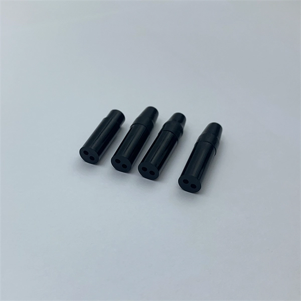
According to different types of pigtail cable connector terminated at the end, there are LC fiber pigtail, SC pigtail, ST pigtail, FC pigtail, fiber pigtail and so on. With different structures and appearance, each of them has their own advantages in diffe. According to different types of pigtail cable connector terminated at the end, there are LC fiber pigtail, SC pigtail, ST pigtail, FC pigtail, fiber pigtail and so on. With different structures and appearance, each of them has their own advantages in different applications and systems. Let's go through some widely used ones. SC Pigtail: SC pigtail. Fiber Optic Pigtails, In fiber optic cable installation, how cables are attached to the system is vital to the success of network. If done properly, optical signals would pass through the link with low attenuation and little return loss. pigtail offers an optimal way to joint optical fiber, which is used in 99% of single-mode applications. This pos. pigtails can be divided into single-mode (colored yellow) and multimode (colored orange) fiber. Multimode pigtails use 62.5/125 micron or 50/125 micron bulk multimode fiber cables and terminated them with multimode fiber optic connectors at one end. 10G multimode fiber cables (OM3 or OM4) are also available in optic pigtails. The jacket color of 10.
[PDF]

The SS64S16A (L-16. 2,SC) is a Huawei high-performance STM-16 optical interface board designed to deliver 2. 5 Gbps long-haul transmission across SDH transport networks. The SFP-FE-SX-MM1310 (part number: 02315233) is a Huawei-certified 100M optical module. However, the Vendor Name field displays the original manufacturer name, instead of HUAWEI. Huawei. Optical modules are widely used in switches, network interface cards (NICs), routers, and other communication devices. During use, reading optical module information helps understand its real-time operating status, enabling faster troubleshooting of link abnormalities. The following uses the. Original SFP Huawei GPON-OLT-CLASS-C+/C++ Optical Module GPON Optical Module A GPON optical module is connected to one SC optical fiber to provide GPON access service. Return Material Authorization (RMA) Process Standard Hardware Warranty Policy: Original new sealed ZTE product: 1 Year The Support. Problem: All optical ports cannot be connected, and the indicator lights are not on. Solution: To solve this problem, you can follow these steps: Check if the fiber and optical modules are compatible. Perform a. Huawei GPON boards include GPON, XG-PON, XGS-PON, XG-PON&GPON Combo, XGS-PON&GPON Combo interface board, so there are these kinds of GPON optical modules corresponding. The following figure shows the optical modules supported by the S5720-12TP-LI-AC. You can also use the Hardware Center to query the.
[PDF]

The 12 cores plastic fiber optic distribution box provides a protected connection point for the feeder cable and drop cable in FTTH and FTTx networks. It integrates optical fibre splicing, splitting, distribution, storage and cable connection in the wall mounted fiber box. The 12 Core Fiber Optic Distribution Box is meticulously crafted using high-quality ABS+ material, guaranteeing exceptional protection and achieving an impressive IP 65 protection level. This sturdy. The 12 Port Fiber Distribution Box can connect up to 2 optical cables, providing space for distributors and 12 fuses. It is equipped with 12 SC adapters and can work in outdoor environments. Data communication networks. The nomenclature “12-SC” explicitly denotes the capacity and interface standard: the. ▶Premium Quality : Featuring our 12-core FTTH Fiber Optic Distribution Enclosure, this Fiber Optic Terminal Box is made from PC+ABS material that ensures its durability and long-lasting life. It is -proof,, and anti-aging, with grade up to IP65, providing for your fibers. ▶Advanced Design : Our.
[PDF]

This video goes over common types of connectors, their respective adapters, and how to properly connect and disconnect them. more Are you interested in seeing how fiber optic connectors get. Unplugging a fiber jack, also known as a fiber optic connector, is a delicate process that requires attention to detail and proper handling to ensure the integrity of the fiber optic cables and connectors. Fiber optics are used in a variety of applications, including telecommunications, internet. If you're wondering how to remove fiber optic cable from connectors, there are a few different ways to do it. You need to know which connector is the correct one for the cable and what kind of wire it's made of. You can also use shears or wire cutters to cut through the connector. This article. Fiber optic connectors are essential components in fiber optic networks, providing a reliable connection between cables and equipment. Removing these connectors requires care to avoid damaging the delicate fibers or the connector itself. To connect a fiber optic cable to SFP optical module, first ensure the SFP is fully inserted into the network port until it "clicks", then remove the dust caps from both the SFP and the LC fiber optic connector.
[PDF]