This chapter presents the development of the Energy Internet throughout the history as an evolutionary solution based on modern technological development and needs, with the respect of its architecture, key features, and key concepts, such as energy router, prosumer, and virtual. This chapter presents the development of the Energy Internet throughout the history as an evolutionary solution based on modern technological development and needs, with the respect of its architecture, key features, and key concepts, such as energy router, prosumer, and virtual. Energy Internet, a futuristic evolution of electricity system, is conceptualized as an energy sharing network. The. ITM University Gwalior, India. coordinating and controlling the many parts of a system, whether they are locally located or geographically dispersed. The study wraps up by outlining the most pressing problems that will need to be solved in order to implement an.
[PDF]
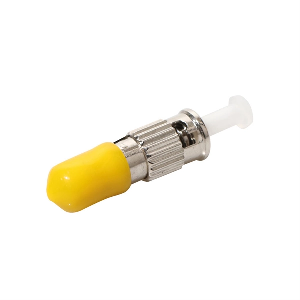
An optical fiber is a cylindrical ( waveguide) that transmits light along its axis through the process of total internal reflection. The fiber consists of a core surrounded by a layer, both of which are made of materials. To confine the optical signal in the core, the of the core must be greater than that of the cladding. The boundary between the core and cladding m.
[PDF]

More specifically, these systems keep tabs on voltage, current, and temperature limits and control the disconnect relay. This allows them to disconnect themselves from the external application in case of malfunction. From a drop of rain to the shining sea, an energy storage system is like the earth's bodies of water (hear us out). In a battery energy storage system (BESS), the energy in the battery cells is like raindrops that combine to form a brook. Made of the combined energy from cells, these brooks combine. Battery energy storage systems (BESSs) investment is expected to grow to $103 billion by 2030. ) Battery systems aren't just designed to serve as local power backups, such as the systems used to power critical facilities (including hospitals and data centers) when the normal. When a 300 MWh battery energy storage system (BESS) in Arizona tripped offline during July's heatwave, operators discovered voltage fluctuations had overwhelmed its protection relays. Could your facility withstand such stress? As global BESS installations surge—projected to reach 1. Protection is necessary when energy and voltages combine from the modules, as well as from the battery racks. Fuses are an efficient. The electrical integration design of a Battery Energy Storage System (BESS) is based on the application scenario and includes various aspects such as DC, high/low voltage distribution, control power distribution, grounding, lightning protection, and safety standards.
[PDF]
The World Bank Group has approved plans to develop Botswana"s first utility-scale battery energy storage system (BESS) with 50MW output and 200MWh storage capacity. The World Bank will support the 4-hour duration BESS via a loan of US$88 million. Botswana has today marked a historic milestone in its energy transformation journey with the groundbreaking ceremony and signing of the Power Purchase Agreement (PPA) for the 500MW Maun Solar Photovoltaic (PV) Plant and 500MWh Battery Energy Storage System (BESS), one of the most ambitious. By 2030, 140MW of BESS will be needed to support the uptake of renewable energy generation. This financial boost will fund the construction of a 100-megawatt solar power plant and support a comprehensive renewable energy program designed to bring. Botswana has received an $88 million loan from the World Bank for its first utility-scale battery energy storage system (BESS). The 50 MW/200 MWh project will allow for the stable integration and management of renewable energy on the nation"s grid. In conclusion, the strategic imperatives. The World Bank has provided Botswana, one of the world's fastest-growing economies, with a loan to finance a 50 MW/200 MWh battery energy storage system, the nation's biggest such project to date.
[PDF]

Primary: The main distribution panel, supplies power from the transformer. Differences Between Primary, Secondary, and Tertiary Distribution Boxes Designed for construction or large-scale projects as a main distribution point. Built to meet specific safety and operational standards for temporary construction sites. Incorporates a complete protection system (e. A feeder usually begins with a feeder breaker at the distribution substation. Many feeders leave substation in a concrete ducts and are routed to a nearby pole. At this. The equipment selection depends on the specific power load requirements. These units help control and protect the electrical circuits that serve things like cabin lighting, entertainment, and climate control. The main goal is to keep the primary systems safe while making sure secondary. What Is a Distribution Box? Types, Uses & How to Choose A distribution box, also known as a power distribution box or electrical distribution box, is used to distribute electrical power safely to multiple circuits. It helps organize, protect, and control electrical connections in residential. The main role of a distribution boxes is to channel electric current from the main supply to different circuits within a building. It also helps keep the electricity supply safe by preventing issues like short circuits and overloads. Most distribution boxes contain circuit breakers or fuses that.
[PDF]

