This chapter presents the development of the Energy Internet throughout the history as an evolutionary solution based on modern technological development and needs, with the respect of its architecture, key features, and key concepts, such as energy router, prosumer, and virtual. This chapter presents the development of the Energy Internet throughout the history as an evolutionary solution based on modern technological development and needs, with the respect of its architecture, key features, and key concepts, such as energy router, prosumer, and virtual. Energy Internet, a futuristic evolution of electricity system, is conceptualized as an energy sharing network. The. ITM University Gwalior, India. coordinating and controlling the many parts of a system, whether they are locally located or geographically dispersed. The study wraps up by outlining the most pressing problems that will need to be solved in order to implement an.
[PDF]

When it comes to testing fiber optic cables, a Visual Fault Locator (VFL) is an essential tool in your toolkit. A VFL is used to detect faults, breaks, or bends in fiber optic cables by emitting a bright red light that is visible even through the fiber's jacket. Let's dive into everything you need to know about mastering VFLs. It's a cost-effective and. Visual Fault Locator (VFL) testing is one of the most fundamental inspection methods used in FTTH, ODN, and data center environments. A VFL emits a visible red laser (typically 650 nm) that travels along the fiber core and leaks out at points of excessive loss, fiber breaks, or microbends. Although. The Fiber Visual Fault Locator Kit is an essential tool for network technicians and engineers; it provides an accurate and quick method of finding such problems as breaks, bends or faults that may affect the network's operation. It works by injecting a visible red laser light (usually in the 650nm wavelength) into the fiber. When the light encounters a fault, such as a break, bend, or bad splice, it leaks out of the fiber, making the. Conducting efficient, repeatable fiber optic cable certification requires an array of specialized test equipment: Optical Loss Test Set (OLTS) – Integrates adjustable light source and power meter for efficient, Tier-1 insertion loss testing. Visual Fault Locators – Handheld devices projecting.
[PDF]

Testing solar panels is easy with a multimeter! To test the current, simply connect the multimeter to the panel's output. Set it to read DC current. To test voltage, set your multimeter to. A $15 multimeter and 5 minutes of testing can diagnose most solar panel problems. Measure Voc (open circuit voltage) — if it reads 0V, the panel or wiring is dead. If it reads 60–80 % of rated, a bypass diode has failed. If Voc is normal but the system is not producing, the problem is downstream. Solar panels are usually tested under standard conditions using a light source that mimics the light from the sun on a clear day. You can use the following method if you want to test your solar panel under standard conditions. We will cover the. A multimeter is a tool that measures the voltage, current, and resistance of an electrical circuit. Fluke recommends using the Fluke 117 Electrician's Multimeter or Fluke 283 FC CAT III 1500 V Digital Multimeter to test solar modules. This helps you spot issues early and keep your system running efficiently. By the end of this guide, you will be equipped with the knowledge to diagnose.
[PDF]
The VFL 30mW 30km tester meter is a powerful and versatile instrument capable of tracing and identifying fiber optic cable faults within a range of 30 kilometers. It employs a 30mW VFL light source, which is more than sufficient for long-distance fiber optic testing applications. This QuickTreX ® high quality visual fault locator (VFL) laser test pen is compact, rugged, and perfect for locating bends and breaks in jacketed or bare fiber within 30Km. It's also great for identifying specific connectors in patch panels. This VFL emits red light by using a 650nm semiconductor. Easy to Check Fiber Faults - This visual fault locator can accurately detect and locate fiber breaks, poor connections, bending, or cracking. The detector will emit a 650nm bright light for fiber tracing, breaks or faults in the fiber will refract the light. PRACTICAL DESIGN AND EXCELLENT FUNCTION –. The Pen Shape Visual Fault Locator (VFL) is a robust, cost-effective fiber optical cable test tool for locating faults within OTDR dead zones. As a visual fault identifier (VFI), it can quickly identify faults in fiber optic jumper cables, distribution frames, patch panels, and splice trays. Using. New: A brand-new, unused, unopened, undamaged item in its original packaging (where packaging is. Packaging should be the same as what is found in a retail store, unless the item was.
[PDF]

In this article, you will learn the step-by-step process of testing your solar panels using a multimeter. We will cover the essential tools you need, the specific measurements to take, and how to interpret the results. A $15 multimeter and 5 minutes of testing can diagnose most solar panel problems. Measure Voc (open circuit voltage) — if it reads 0V, the panel or wiring is dead. If it reads 60–80 % of rated, a bypass diode has failed. By the end of this guide, you will be equipped with the knowledge to diagnose. Learning how to test solar panel with multimeter is useful for homeowners, technicians, farmers, and anyone using solar energy systems. A digital multimeter allows you to check voltage, current, continuity, and resistance. Fluke recommends using the Fluke 117 Electrician's Multimeter or Fluke 283 FC CAT III 1500 V Digital Multimeter to test solar modules. Here's how a technician tests solar modules with a multimeter:. A multimeter is an indispensable tool for anyone working with solar panels, allowing for accurate measurements and diagnostics. It empowers users to assess the performance, identify faults, and ensure optimal energy production. Perfect for DIY solar builders, RV owners, o. more Audio tracks for some languages.
[PDF]
An OTDR is a powerful tool that helps technicians and engineers assess the health of fiber optic cables. OTDRs inject high-powered light pulses into the fiber using specialized laser diodes. As these light pul.
[PDF]
This study presents the experimental investigations on heat transfer and airflow in a closed refrigerated display cabinet. Air and product temperatures and air velocity were measured with thermocouples and.
[PDF]

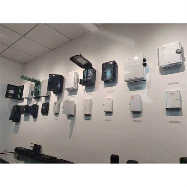
They function as junction points that manage, protect, terminate, and distribute fiber optic cables, ensuring efficient data transmission between different network elements. Wall-mount and pole-mount fiber boxes represent two installation categories within ODN infrastructure, each designed to withstand different mechanical forces, environmental exposure, and cable-routing geometries. Although both serve as distribution nodes for FTTH and PON networks, their structural. Fiber Distribution Boxes (FDBs) are critical components in modern telecommunications infrastructure, particularly in fiber optic networks. These enclosures protect and organize fiber splices, connections, and splits in aerial networks, ensuring reliable signal transmission across residential, commercial, and remote. A fiber optic distribution box, also known as a fiber optic terminal box or fiber optic termination box, is a device used to connect and manage fiber optic cables in a network. It serves as a central point for fiber optic cable termination, splicing, and distribution. The distribution box provides. desire to become a Clearfield partner. Designed for the outside plant environment, these cabinets provide a single distribution point to depl y FTTH in urban or dense neighborhoods.
[PDF]
In , a busbar (also bus bar) is a metallic strip or bar, typically housed inside,, and for local high current power distribution, transmission, or switching substations. They are also used to connect high voltage equipment at electrical switchyards, and low-voltage equipment in. They are generally uninsulated, and have sufficient stiffness to be s.
[PDF]
A fiber-optic sensor is a that uses either as the sensing element ("intrinsic sensors"), or as a means of relaying signals from a remote sensor to the electronics that process the signals ("extrinsic sensors"). Fibers have many uses in. Depending on the application, fiber may be used because of its small size, or because no is needed at the remote location, or because many sensors can be along the length of a fiber by using light wavelength shift for.
[PDF]

An elevator data communication system is configured to communicate between a plurality of elevator systems and a datacenter remotely located from the plurality of elevator systems. WAN – Wide area network is similar to a LAN but is not limited to a single location. It can also consist of several LANs which are interconnected. Usually, it is the only way how to contact the outside world and get help when you are trapped in the elevator. But many changes and exciting new challenges are coming in the field of elevator. “THE LONGEST RUNNING PUBLICATION FOR THE VERTICAL TRANSPORTATION INDUSTRY SINCE 1953. ” Open and standard communication protocols are vital for interoperability in building automation and elevators. The OSI seven-layer model frames protocol design but compliance alone does not guarantee. Elevators are essential in most modern buildings, but they need communication systems that meet code requirements. Here's how new features are making compliance easier—and delivering a new revenue stream. More sophisticated and effective communication solutions are needed to manage the increasing. Technical systems are, in general, becoming ever more complex. Electronic systems – usually equipped with tiny embedded microprocessors – are implementing new functions, increasing convenience or improving system safety and reliability.
[PDF]

Protective relays are essential devices used in electrical power systems to detect faults and abnormal conditions, initiating corrective actions to prevent equipment damage and ensure system stability. These relays play a crucial role in the protection of transformers, generators, transmission. A protective relay is an intelligent device that senses abnormal electrical conditions, such as overcurrent, under-voltage, or frequency deviations. It initiates the operation of circuit breakers to isolate the affected section. This prevents damage to equipment, reduces downtime, and safeguards. Protective relays are critical components in power systems, providing essential protection for various elements such as generator sets, outgoing feeder and load networks, and incoming utility sources. It functions as a watchdog by constantly surveying multiple system components including voltage, current, frequency, and phase angle. It. Protective relays and devices have been developed over 100 years ago to provide “lastline”of defense for the electrical systems. They are intended to quickly identify a fault and isolate it so the balance of the system continue to run under normal conditions. The selection and applications of.
[PDF]

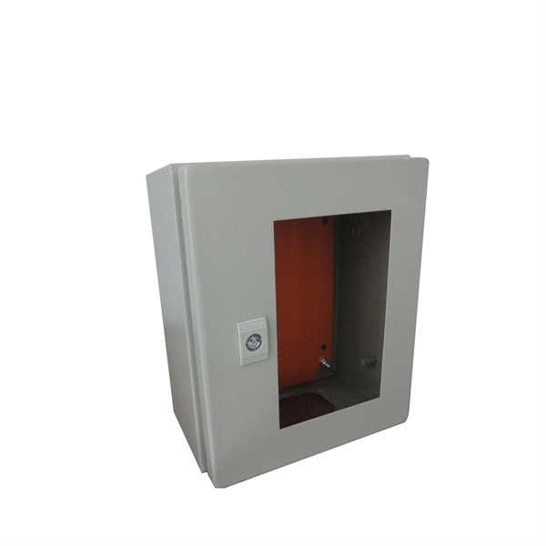
Primary: The main distribution panel, supplies power from the transformer. The terms primary, secondary, and tertiary distribution boxes are relative. Let's make an example for clarity: A newly constructed residential area introduces a 10kV power line to a substation. From the transformer's low-voltage side (0. Spot Networks are used for customers with the highest reliability requirements. This configuration connects two or more transformers (fed from at least two. A complete set of products can form a complete construction electricity three-level protection system, to achieve the purpose of one machine, one gate, one protection. The secondary box is designed with inside and outside doors and sprayed with plastic. Safe and beautiful, waterproof box top. These smaller breaker panels, also known as sub-distribution boards, are commonly used to provide power to secondary circuits within a building. Understanding the components and wiring configuration of an electrical sub panel is essential for safe and efficient electrical installations. In this. ACS takes the basic idea of zone wiring and combines it with pre-cut, pre-tested cable and plug-in connectors, to provide power and telecommunication systems that can be installed under raised floors (The Intelligent Floor), or in accessible ceilings (The Intelligent Ceiling). installed under.
[PDF]