
Welcome to our channel! In this video, we'll walk you through the process of wiring a home distribution box with a detailed connection diagram. What is Distribution Board? Distribution board. These smaller breaker panels, also known as sub-distribution boards, are commonly used to provide power to secondary circuits within a building. Understanding the components and wiring configuration of an electrical sub panel is essential for safe and efficient electrical installations. In this. Primary distribution systems consist of feeders that deliver power from distribution substations to distribution transformers. A feeder usually begins with a feeder breaker at the distribution substation. Many feeders leave substation in a concrete ducts and are routed to a nearby pole. This breaker must be compatible with both your main system and the additional connections. Typically, a 60-amp or 100-amp breaker will be suitable, depending on the load requirements. It includes isolator, RCCB (Residual current circuit breaker) or RCD (Residual-current device) devices, protective fuses or MCB's (Miniature Circuit Breaker).
[PDF]

This AutoCAD DWG file includes a complete Single Line Diagram (SLD) of a Distribution Board, showing circuit breakers, wiring connections, and load distribution for lighting, power, and mechanical systems. An electrical panel box, also known as a breaker box or a distribution board, is a crucial component of any electrical system. It serves as a central hub for distributing electricity throughout a building, ensuring that power is delivered safely and efficiently to all the required locations. Whether you're an electrician or a DIY enthusiast, this guide will help you understand the basics of home electrical distribution. What is Distribution Board? Distribution board. Welcome to our channel @Electricalgenius In this video, we'll take you through a detailed step-by-step guide on wiring a home distribution DB (Distribution Board) box. A distribution board (also known as a service panel or breaker box) is a centralized collection of circuit breakers, fuses, and/or relays used to control and protect the wiring in a home. The diagram. To understand how a breaker box works, it is helpful to have a wiring diagram that shows the connections between the various components. At the heart of a breaker box is the main breaker, which controls the flow of electricity from the utility into the building. This breaker is connected to a.
[PDF]
This chapter presents the development of the Energy Internet throughout the history as an evolutionary solution based on modern technological development and needs, with the respect of its architecture, key features, and key concepts, such as energy router, prosumer, and virtual. This chapter presents the development of the Energy Internet throughout the history as an evolutionary solution based on modern technological development and needs, with the respect of its architecture, key features, and key concepts, such as energy router, prosumer, and virtual. Energy Internet, a futuristic evolution of electricity system, is conceptualized as an energy sharing network. The. ITM University Gwalior, India. coordinating and controlling the many parts of a system, whether they are locally located or geographically dispersed. The study wraps up by outlining the most pressing problems that will need to be solved in order to implement an.
[PDF]

Fiber optic network diagrams represent the architecture and connectivity of fiber optic systems, and their design philosophy integrates technical, functional, and conceptual aspects. The diagrams abstract complex details of fiber optic systems to make them. Fiber optic network design refers to the specialized processes leading to a successful installation and operation of a fiber optic network. It includes first determining the type of communication system (s) which will be carried over the network, the geographic layout (premises, campus, outside. A fiber optics network diagram illustrates how high-speed data travels from an internet service provider to end users. These diagrams help engineers plan infrastructure for residential and commercial buildings. What is fibre network mapping? Fibre network mapping is a critical process in the planning, deployment, and management of fibre optic networks. I'm needing symbols for common fiber optic components, cables, connectors, backbone ports, etc. Can anyone help me out? Some examples of a diagram would also help. 10-27-2018 01:41 AM Do you know if there's some symbol standard. Definition: Fiber optic cable is also called the “ Optical Fiber Cable “, and it is simply Ethernet networking cable that contains the multiple optic fibers, and they allow to transmit data with massive volume. Main goal of designing the optical fiber cable is to offer ultra performance data.
[PDF]
In this article, we will provide a detailed wiring diagram for a radiator electric fan, along with step-by-step instructions on how to install it. The wiring diagram for a radiator electric fan consists of several components, including a relay, a fuse, a temperature switch, and. Your Infinitybox IPM1 Kit makes it easy to control your cooling fan. The MASTERCELL NGX takes the trigger signal from your temperature switch or ECU. It sends a command over the CAN network to the front POWERCELL to turn the cooling fan on and off. The POWERCELL has the switching and fuse. Wiring should only be performed by a trained electrician to prevent injury or death. Install manual disconnect switch inside building adjacent to fan. Route all wires to include drip loops and secure. Drip loop will drain accumulated moisture away from motors, controls, and other electronic. Wiring Harnesses, Electric Fan Controls, Accessories, Grounding, Lighting, Switches, Fuel Injection Harnesses, Wiring Aids and More!. However, the process of installing an electric fan can be overwhelming, especially if you're new to automotive wiring.
[PDF]

In this video, we'll walk you through the process of wiring a home distribution box with a detailed connection diagram. In this article, we will delve into the details of an electrical sub panel diagram, discussing the various components, their functions, and the proper wiring techniques. Whether you are a homeowner tackling a DIY electrical project or an electrician looking to expand your knowledge, this guide will. A 30-amp sub panel functions as a secondary electrical distribution point, receiving power from the main service panel to serve a localized area. This small panel is commonly used to provide lighting and receptacle power to detached structures like a garage, a workshop, or a small shed. more Welcome to our channel! In this video. Load Calculation: Perform a load calculation to determine the total electrical load of the building. This involves calculating the power requirements of each individual device or system and adding them together to get the total load. It is important to ensure that the wiring and subpanel can handle. An electrical panel box, also known as a breaker box or a distribution board, is a crucial component of any electrical system. It serves as a central hub for distributing electricity throughout a building, ensuring that power is delivered safely and efficiently to all the required locations. ) is a cabinet or cutout box which contains on controlling and protective devices (such as circuit breakers, fuses, switches etc.
[PDF]
Directory of 84 fiber optic cable manufacturers in the US. Find fiber optic cable assemblies, connectivity products, and subsea cables, plus contact info and. Buyers seek manufacturers to solve challenges like achieving specific optical return loss (ORL) targets for. Thomas has been North America's number one industrial sourcing platform for more than 125 years. You can filter these companies by location, certifications, and more factors to easily find and connect with the right. 171 Fiber Optic Cable manufacturers listed. Fiber optic cable is composed of two layers of glass, the core, which carries the actual light signal, and the cladding, which is a layer of a glass surrounding the core. Narrow down on the. Find 1,029 Fiber Optic Cables suppliers with GlobalSpec. Our catalog includes 106,451 manufacturers, 20,792 distributors and 94,628 service providers. Charlton Precision. The data fields provide comprehensive information including a description of the Fiber Optical Cable product, its HSN code, shipment date, price, quantity, countries of origin and destination, ports of origin/destination, details of Suppliers and Buyers, and top decision makers' contact.
[PDF]

This guide is intended to present the fundamentals of power system design for commercial and industrial power systems. A distribution board, also known as a panel board or breaker panel, is an enclosure that houses electrical components such as circuit breakers, fuses, and busbars. Its primary function is to distribute electrical power from a main supply to various circuits while providing protection against. These Distribution Boxes enable decentralized installation of the electronics close to the load. The range of applications extends from pure energy distribution in buildings to building automation and through to industrial plants. SMART DISTRIBUTION BOXES FOR FLEXIBLE BUILDINGS. It is a vital part and central hub of any electrical system. Whether it's a home, office, or factory. Electrical distribution system design is a critical aspect of industrial facility engineering that determines how electrical power is delivered from the utility service to end-use equipment. A well-designed distribution system provides reliable power, adequate capacity, proper protection, and. In industrial power distribution systems, cable distribution boxes (also known as power distributor boxes, distribution electrical boxes, or electrical power distribution boxes) are the core hub of power transmission, branching, and protection. Its layout directly affects the efficiency of the.
[PDF]

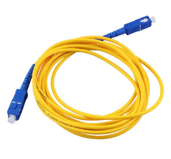
Basic: 300 ft indoor run, standard SC connectors, no trenching. 00/ft, Termination $2. Total: about $2,020; per-foot average around $6. 13 per foot, while a 288-count optical fiber cable for building backbones can reach $6 per foot or more. Pre-terminated assemblies and patch cables incur higher costs due to factory termination, with prices varying by connector type and the number of. The price of fiber optic cabling depends on cable type, length, installation method, and surrounding materials. Typical costs hinge on fiber count, indoor versus outdoor use, and whether trenching, splicing, or termination is required. This guide provides practical ranges in USD and practical price. ⚠️ Note on Units: Prices below are primarily listed Per Meter. We have included Per Foot conversions for reference (1 Meter ≈ 3. Best For. * Disclaimer: Prices fluctuate based on raw material indices (Glass/Copper/Polymer) and cable core count (e. Breakdown of. CRU provides comprehensive, accurate and up-to-date price assessments and research reports for bare optical fibre across various key regional markets, combined with insights into the factors and events affecting markets. Understanding cost and price helps set a realistic budget from the start. Indoor simple run vs armored outdoor, single-mode. Assumes standard jacket; higher if submittal specs require specialty fiber. Higher with high-precision connectors.
[PDF]
In this comprehensive guide, we will walk you through the step-by-step process of wiring outdoor outlets safely and effectively. 💡 Quick Answer: An outdoor electrical junction box is a weatherproof enclosure where electrical wires connect or split, required by code to protect connections from moisture, provide safe access for maintenance, and prevent electrical hazards in exterior applications. Properly wiring outdoor outlets enhances safety, functionality, and convenience. However, because outdoor electrical work involves. Installing an outdoor electrical panel box requires careful planning and execution. This guide covers everything you need to know for a safe installation. Understanding local electrical codes is paramount; these regulations ensure safety and compliance. Using the right tools, such as a voltage. Outdoor wiring faces harsher conditions than indoor installations as it is exposed to moisture, sunlight, and mechanical damage. Outdoor Receptacles (NEC 210. 9. An outdoor breaker box with integrated outlets is a specialized electrical assembly that serves as a weather-rated subpanel or load center. Designed for exterior use, it often features pre-wired receptacles directly on the enclosure. It takes the incoming power and safely distributes it to different circuits throughout your building. However, the key to.
[PDF]

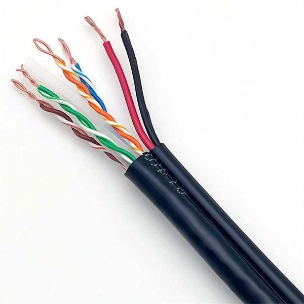
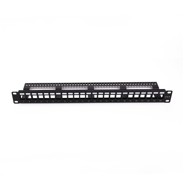
This document provides direction on properly identifying the ribbon and individual fiber in the AFL Wrapping Tube Cable. Depending on fiber-count, ribbon band-marking (striping) and binder group count will differ. The number of optical cores in an optical fiber is the total number of equipment interfaces multiplied by 2, plus 10% to 20% of the spare quantity, and if the communication mode of the equipment has serial communication and equipment multiplexing, you can reduce the number of cores. The number of. A fiber optic patch panel is a critical piece of equipment used to organize, manage, and connect fiber optic cables within a network. It serves as a central hub where multiple fiber optic cables can be routed, terminated, and interconnected to various network devices such as switches, servers, or. Fiber optic cables are essential to modern networks, enabling high-speed and reliable data transmission. Among their many features, the number of fiber cores directly affects data capacity and network performance. Understanding this key aspect is crucial for making the right choice. This post will guide you through understanding fiber optic cores and selecting the perfect cable for.
[PDF]

6 core Fiber Optical Splicing With 24 Port LIU || Full Installation || Beginner Watch this video Fiber optic splicing is the process of joining two fiber optic cables together to create a conti. more. In this article, we'll explain how to connect multiple Ethernet switches using fiber optic cables and the equipment required for this to work. Network topology refers to the way in which the links and nodes of a network are arranged in relation to each other. Simply put, it defines how network. Choose an SFP module based on the fiber optic cabling that will be connected to the network switches. SFP transceiver modules almost always require two fiber optic cable strands. Most modern SFP transceiver modules. Most modern fiber-enabled network switches require an SFP transceiver module featuring a duplex (two strand) multimode OM3 or duplex single mode OS2 connection with LC connectors. Direct attach cables with pre-terminated SFP connections may also be used. Download the Application PDF SFP transceiver. This article will guide you through the necessary tools, materials, and methods on how to connect fiber optic cables effectively, ensuring you achieve optimal performance from your fiber optic network. These diagrams help engineers plan infrastructure for residential and commercial buildings. By using light signals, fiber optics provide faster speeds and better reliability than.
[PDF]

In this guide, you will find a chronological description of the fusion splicing process, the principal technical standards, and answers to the real-life questions network engineers and procurement teams may have. In this guide, we cover the basics of fiber optic splicing, how to perform splicing using two different methods, and finally some best practices to perform good fiber splicing. What is Fiber Optic Splicing and Why is it Needed? – #1. Use and Maintain Your. This Geoschematics drawing remains easy to read despite containing more than 2000 fibers and 500 splices. Splice Diagrams or Matrices capture an electric or optical network inside a location – documenting cables, ported equipment, and connections. Splices are fiber-to-fiber, port-to-fiber and. This guide will walk you through the complete process of fiber optic splicing—covering each step in detail so you can deliver a clean, professional splice every time. Before jumping into the physical steps, it's important to understand the two primary methods of fiber splicing: fusion splicing and. Page 1 The FOSC 450 fiber optic splice closures use compressed-gel cable seals to environmentally seal fiber cable splice points. FOSC 450-ab-c-dd-e-fgh The maximum single splice capacity of the FOSC 450 B6 closure is a = Closure size 144 with 24 splices stored on six trays. Therefore, we will also touch on cost factors, risk management, and best practices in.
[PDF]
