When it comes to testing fiber optic cables, a Visual Fault Locator (VFL) is an essential tool in your toolkit. A VFL is used to detect faults, breaks, or bends in fiber optic cables by emitting a bright red light that is visible even through the fiber's jacket. Let's dive into everything you need to know about mastering VFLs. In the. Finding a break in a fiber optic cable can be challenging but is essential for maintaining a stable network. Common Indicators of a Cable Break Signal. Here Kingfisher's experienced engineers share their experience in best practices and procedures for fiber optic testing related mostly to installation and maintenance. We hope that by sharing our knowledge, we will help grow our industry. Please enjoy & pass on these notes. The following are key methods and techniques used for optical fiber cable line failure positioning: Visual Inspection: Perform a visual inspection of the. Locating faults in fiber optic cables requires specialized tools and techniques. Look for dirt, scratches, or damage on the connectors. Clean. To ensure the quality and continuity of fiber optic services, it is essential to identify and locate fiber optic cable faults as quickly and accurately as possible. In this article, you will learn about some of the common methods and tools for fiber optic testing and troubleshooting.
[PDF]
This chapter presents the development of the Energy Internet throughout the history as an evolutionary solution based on modern technological development and needs, with the respect of its architecture, key features, and key concepts, such as energy router, prosumer, and virtual. This chapter presents the development of the Energy Internet throughout the history as an evolutionary solution based on modern technological development and needs, with the respect of its architecture, key features, and key concepts, such as energy router, prosumer, and virtual. Energy Internet, a futuristic evolution of electricity system, is conceptualized as an energy sharing network. The. ITM University Gwalior, India. coordinating and controlling the many parts of a system, whether they are locally located or geographically dispersed. The study wraps up by outlining the most pressing problems that will need to be solved in order to implement an.
[PDF]
A distribution box, or DB box, is a circuit breaker enclosure. It is a vital part and central hub of any electrical system. The hub distributes electrical power from a single input source to various circuits throughout a building. A distribution box, also known as a power distribution box or electrical distribution box, is used to distribute electrical power safely to multiple circuits. Distribution. A distribution boxes is an essential device that manages the safe and efficient flow of electrical power throughout different areas of a building or facility. Today, electrical systems are essential for homes and industries. It is widely employed in residential, commercial and industrial set-ups for circuit control and protection. By knowing their great.
[PDF]

In this guide, learn the basics of reading and interpreting electrical wiring diagrams. Follow Along on SkillCat: "Wiring Diagrams" Course! Want to test your knowledge? Skip to the quiz!. In this article, you'll learn how to read, understand and use a wiring diagram. An electrical wiring diagram could be a single page schematic of how a ceiling fan should be connected to the power source and its remote switches. A wiring diagram may include the wirings of a vehicle. For example, how. Electrical wiring diagrams are an essential tool for electricians, engineers, and automation technicians. Proper interpretation is crucial for understanding the operation of devices, diagnosing faults, and working safely with electrical installations. Understanding how to read electrical diagrams. In order to trace control system problems to the core, the ability to read and interpret various resources, from facility-level diagrams to machine-level wiring layouts, is critical. The engineering world is crammed full of drawings and diagrams of every possible kind. It shields sensitive equipment from dust, moisture, and. After reading and studying this handbook, electricians (or would-be electricians) will have a firm grasp on the many symbols used in electrical diagrams.
[PDF]

The ring main circuit is commonly used for powering lighting circuits and plug sockets in residential and commercial buildings. It provides a safe and reliable method of electrical distribution, ensuring a consistent supply of power to each outlet. WATERPROOF DISTRIBUTION BOX: The power socket distribution box is made of high-quality ABS plastic material, with a size of 9. The waterproof grade of the shell is IP65. It is equipped with 4 IP44 waterproof sockets., can. The distribution box (DB box) helps safely and efficiently distribute electrical power. Today, electrical systems are essential for homes and industries. But what exactly is a power distribution box, and why is it so essential in our daily lives? The DB panel board controls the flow of electricity. Also known as a distribution board or breaker panel, it acts as the control hub, distributing power to different circuits and protecting them from overloads and faults. Here, we'll delve into what an electrical distribution box is, how it. Portable distribution boxes are mainly composed of core components such as shells, circuit breakers, sockets, terminals, leakage protectors, fuses, etc. As a protective "armor", the shell is mostly made of high-strength engineering plastics or aluminum alloys. Understanding the ring main circuit diagram is essential for electricians and individuals involved in electrical installations and repairs. The ring main circuit consists of a loop of cable, which.
[PDF]

The circuit diagram of the protective relay is made up of current transformer primary windings, current transformer secondary windings, relay operating coils, circuit breakers, and the tripping circuit. The relays are in round glass cases. The rectangular devices are test connection blocks, used for testing and isolation of instrument transformer circuits. In electrical engineering, a protective relay is a relay device designed to trip a circuit breaker when a fault is detected. : 4 The first. The working of a protective relay is based on continuous monitoring of electrical quantities such as current, voltage, frequency, and power. A typical protective relay circuit is shown below: Protective Relay Circuit Diagram The first part of the circuit consists of the primary winding of a CT. A relay is a four-terminal electrical switch, used to control any electrical circuit with an independent low-power signal and also to control various electrical circuits with a single signal. The terminals of the relay mainly include; common, coil, NO (normally open) & NC (normally closed). It functions as a watchdog by constantly surveying multiple system components including voltage, current, frequency, and phase angle. During a fault condition, there is a change. Protective relays and devices have been developed over 100 years ago to provide “lastline”of defense for the electrical systems.
[PDF]

When a circuit breaker keeps tripping, the cause usually falls into one of three categories: overloads, short circuits, or ground faults. The key is knowing what's driving each one so you can troubleshoot it correctly. This comprehensive guide, compiled by ELECO's technical support team based on decades of global field experience, provides a clear, actionable roadmap to identify and solve the five most common causes of frequent tripping, saving you time and ensuring compliance on any international project. The bottom line: A tripping breaker means your electrical system is doing exactly what it's supposed to do. Now we need to figure out why. Understanding which one you're dealing with helps you know if this is something you can handle or if you need. Circuit breakers serve as your home's electrical guardians – they automatically cut power when detecting dangerous conditions. Occasional tripping is normal protection behavior, but frequent tripping signals underlying issues needing attention. It's a typical issue. Below, you'll find reasons why this occurs and tips to avoid it moving forward. Get a handle on your circuit breaker problems! Circuit breakers are protection.
[PDF]

This SFP module provides 20km transmission distance over single-mode fiber at a nominal wavelength of 1310nm. The transmitter section uses a 1310nm FP laser that is a class 1 laser compliant according to International Safety Standard IEC 60825. A 1310nm optical module lets you move data efficiently through fiber optic communication networks. As part of the O-band (1260–1360 nm), it balances low dispersion, stable performance, and cost efficiency. This makes it widely adopted in data centers, enterprise backbones, and metro access. The transmission distance of optical modules is divided into short distance, medium distance, and long distance. Transmission distances greater than or equal to 30km are considered long-distance transmissions. Light commonly used in optical fiber is 850nm. The GPON OLT SFP transceiver provides an asymmetric 1. 244Gbps upstream and 2. 488Gbps downstream, reaching a link up to 20km over SMF via SC/UPC connector. It can operate at temperatures between -40°C and 85°C. Digital optical monitoring (DOM) support is also present to allow access to real-time.
[PDF]
The zinc plating on these tray systems offers good corrosion resistance. Cut, bend, and connect the wire mesh trays to route cable and hose in configurations such as curves, slopes, and tees. They are a ligh.
[PDF]

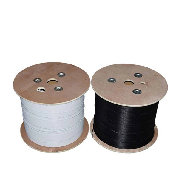
Our selection includes three main fiber variants: 9/125um single mode, 62. 5/125 multimode, and 50um OM3, OM4, and OM5. These pigtails feature premium-grade jackets and are equipped with LC, SC, ST, and FC connectors, typically with a 0. 9mm outer diameter cable. FS fiber optic pigtails offer a fast way to make fiber optic communication devices in the field by fiber splicing, fully manufactured and tested by industrial standards. Our premium pigtails offer low insertion loss and custom length options. Economy pigtails offer over a. Executive Summary: A fiber optic pigtail is one of the most commonly specified yet least understood components in structured cabling. Get the wrong connector type, the wrong polish, or skip proper fusion splicing technique—and you're looking at elevated signal loss, increased back reflection, and a. Fibertronics, Inc. offers a range of competitively priced fiber optic pigtails. In such contemporary fiber optic communication systems, low-loss, and connectivities, which have reliability, are crucial for not only maintaining high-speed but also high-quality data transmission. We stock a wide variety of pigtail fiber types, including single mode and multimode, with all major connector options like SC, LC, ST, and FC available with UPC or APC polish. Ensure a reliable, low-loss.
[PDF]

Splice Diagrams or Matrices capture an electric or optical network inside a location – documenting cables, ported equipment, and connections. Splices are fiber-to-fiber, port-to-fiber and port-to-port. Fiber optic cable splicing involves joining two fiber optic cables together. Another method of connecting optical fibers is termination or connectorization, which consists of processing the end of a fiber optic bundle so that it can be connected to other fibers or devices through fiber optic. In this guide, we cover the basics of fiber optic splicing, how to perform splicing using two different methods, and finally some best practices to perform good fiber splicing. Ensure Your Splicing Tools are Clean – #2. Use and Maintain Your. What to show on a network diagram? Fiber optic network diagrams represent the architecture and connectivity of fiber optic systems, and their design philosophy integrates technical, functional, and conceptual aspects. The diagrams abstract complex details of fiber optic systems to make them. This Geoschematics drawing remains easy to read despite containing more than 2000 fibers and 500 splices. All students and instructors must wear safety glasses in this lab. It is copyrighted by the FOA and may not be distributed without FOA permission. This VHO covers similar material to the videos on YouTube. The lab manual has several.
[PDF]

Protective relays are essential devices used in electrical power systems to detect faults and abnormal conditions, initiating corrective actions to prevent equipment damage and ensure system stability. These relays play a crucial role in the protection of transformers, generators, transmission. A protective relay is an intelligent device that senses abnormal electrical conditions, such as overcurrent, under-voltage, or frequency deviations. It initiates the operation of circuit breakers to isolate the affected section. This prevents damage to equipment, reduces downtime, and safeguards. Protective relays are critical components in power systems, providing essential protection for various elements such as generator sets, outgoing feeder and load networks, and incoming utility sources. It functions as a watchdog by constantly surveying multiple system components including voltage, current, frequency, and phase angle. It. Protective relays and devices have been developed over 100 years ago to provide “lastline”of defense for the electrical systems. They are intended to quickly identify a fault and isolate it so the balance of the system continue to run under normal conditions. The selection and applications of.
[PDF]

Primary: The main distribution panel, supplies power from the transformer. Differences Between Primary, Secondary, and Tertiary Distribution Boxes Designed for construction or large-scale projects as a main distribution point. Built to meet specific safety and operational standards for temporary construction sites. Incorporates a complete protection system (e. A feeder usually begins with a feeder breaker at the distribution substation. Many feeders leave substation in a concrete ducts and are routed to a nearby pole. At this. The equipment selection depends on the specific power load requirements. These units help control and protect the electrical circuits that serve things like cabin lighting, entertainment, and climate control. The main goal is to keep the primary systems safe while making sure secondary. What Is a Distribution Box? Types, Uses & How to Choose A distribution box, also known as a power distribution box or electrical distribution box, is used to distribute electrical power safely to multiple circuits. It helps organize, protect, and control electrical connections in residential. The main role of a distribution boxes is to channel electric current from the main supply to different circuits within a building. It also helps keep the electricity supply safe by preventing issues like short circuits and overloads. Most distribution boxes contain circuit breakers or fuses that.
[PDF]