
The proper installation of a distribution box involves placing it at the right height to ensure safety and convenience. 7 meters) high makes it easily accessible without the need to bend or stretch excessively. (1) Elevator driving machines, motor generator sets, controllers, and auxiliary control equipment shall be installed in a room or enclosure set aside for that purpose. This height also safeguards the box from potential. The work space shall be clear and extend from the grade, floor or platform to a height of 6 1 / 2 feet or the height of the equipment, whichever is greater. The electrical equipment itself may have a height that is less than 6 1 / 2 feet, but if it is mounted so the top of the equipment is higher. Overcurrent devices and disconnects must be located in machine or control spaces, be lockable and provide a single means to disconnect ungrounded conductors, with selective coordination for multi-elevator feeders. Conductor and wireway fill, approved flexible traveling cables and secure supports. Choose the right box based on environment (indoor/outdoor), load capacity, and durability. Check for proper IP/NEMA ratings and material quality. Ensure safe placement: install in dry, accessible areas with good ventilation and at appropriate height (typically ~1. Practice good wiring: secure.
[PDF]

The zero-buoyancy rov cable was born as a power connection and control of underwater robot equipment, as well as signal transmission and feedback link cable applications. The zero-buoyancy cable has been tested by the market and practice due to its excellent. The global underwater zero buoyancy cable market is experiencing robust growth, driven by the expanding offshore energy sector, increasing demand for subsea infrastructure development, and advancements in underwater communication technologies. Linden Photonics is renowned for its innovative fiber-optic solutions, specifically designed for Remote Operated Vehicles (ROVs). These ROV tethers are crucial in underwater applications, offering high performance, durability, and reliability in challenging environments. For use with ROV's (Remote.. Customizable neutral buoyancy fiber optic power cable for ROVs and underwater drones. High‑performance hybrid design combining power and data in one composite cable. Engineered for seawater resistance, flexibility and subsea reliability. Suitable for inspection systems, subsea cameras and. At Invocean, we understand the increasing demands and the critical nature of Remotely Operated Vehicles (ROVs) in various industries such as underwater construction, surveillance, salvage, and scientific research. To support these high-performance tasks, ROVs and Micro-ROV's require reliable.
[PDF]

The primary problem encountered is signal loss, also known as attenuation. Attenuation can be due to absorption, scattering, or bending losses, affecting the quality and speed of data transmission. Attenuation in fiber optic cables is the reduction in signal strength during. To be able to judge whether a fiber optic cable plant is good, one does a insertion loss test with a light source and power meter and compares that to an estimate of what is a reasonable loss for that cable plant. The estimate, called a "loss budget" is calculated using typical component losses for. F iber optic networks rely on the efficient transmission of light signals to deliver high-speed data over long distances. However, various factors can cause signal degradation, leading to performance issues and reduced network reliability. Fiber optic signal loss, also known as attenuation, occurs. A significant signal loss in the optical fiber can cause unreliable transmission. How can we know the value of losses on the fiber link? Read on, this post will teach you how to calculate the losses in optical fiber and judge the fiber link performance. The uses various types of network cables, including multimode and single-mode fiber-optic cable. It can also break your connection. High attenuation makes your system not work well. You should fix it fast to get speed and stability back. > You can solve this with simple steps.
[PDF]
This chapter presents the development of the Energy Internet throughout the history as an evolutionary solution based on modern technological development and needs, with the respect of its architecture, key features, and key concepts, such as energy router, prosumer, and virtual. This chapter presents the development of the Energy Internet throughout the history as an evolutionary solution based on modern technological development and needs, with the respect of its architecture, key features, and key concepts, such as energy router, prosumer, and virtual. Energy Internet, a futuristic evolution of electricity system, is conceptualized as an energy sharing network. The. ITM University Gwalior, India. coordinating and controlling the many parts of a system, whether they are locally located or geographically dispersed. The study wraps up by outlining the most pressing problems that will need to be solved in order to implement an.
[PDF]

Telescopic mast system with advanced vibration-dampening technology to minimize jitter and ensure stable communication and data transmission, even in the most demanding terrain and vehicle movements. Fireco designs and manufactures the most comprehensive line of standard and custom telescopic masts using high quality materials with industry leading engineering and quality testing practices to provide our customers with the world's best mobile masts. Will-Burt's telescopic masts and tower systems provide intelligent. Telescopic mast systems play a critical role in modern field operations—enabling elevation of cameras, antennas, lights, sensors, and communication gear in demanding environments. Whether for surveillance, broadcasting, defense, or emergency response, choosing the right mast system ensures reliable. Floatograph, along with its utility industry partner, Eversource Energy, developed the Rapid Pole® – Temporary Power Pole system to reduce customer downtime, allowing crews to re-energize a circuit in as little as 20 minutes. Floatograph's masts come in height options from 10 to 100 feet, and are. Advanced telescopic mast solutions designed for versatility in the field, providing crucial support for on-the-move (OTM) missions. Erecting the Telescoping Mast is made by simply connecting guys and brackets to the attached unique heavy duty rolled edge guy rings and clamps, extend the sections, insert the locking cotter pins, rotating the tubes to.
[PDF]

West Port Middle East specializes in engineering and supplying cable management solutions that meet the precise requirements of electrical contracting projects across the GCC. Unigroup offers a line-up of high-performance cable trays, Trunking and Channel Systems for all your cable routing requirements. Our cable tray systems are engineered for modern infrastructure, ensuring safe, organized, and efficient cable routing across commercial, industrial, and utility. Cable Trays are support systems used in building electrical wiring. These cable support systems are commonly used to support insulated power and communication cables. Cable trays provide a more preferable alternative to electrical conduit systems and open wiring. Cable tray systems are generally. Premium Construction: Made from galvanized steel, stainless steel, or aluminum, these trays resist corrosion and provide high load-bearing capacity in harsh conditions. From residential towers to industrial plants, our extensive portfolio of products and accessories is designed to provide. A form of cable management system used for supporting and arranging electrical cables and wires in commercial, industrial, and residential structures is known as GI Cable Tray, also known as Galvanized Iron Cable Tray.
[PDF]

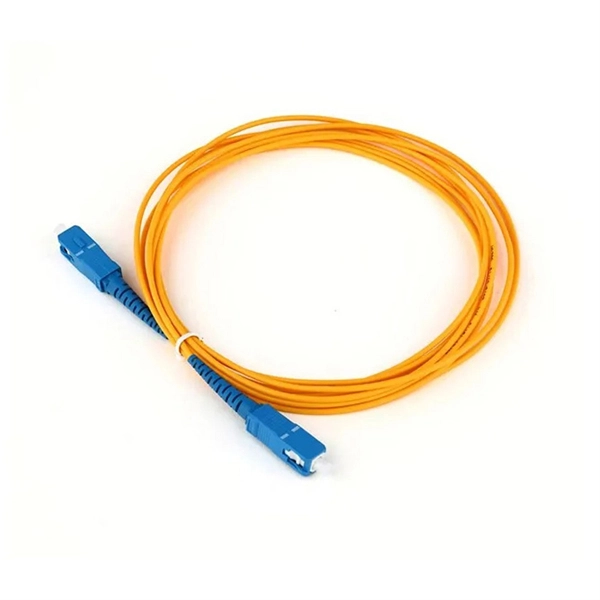
Every fiber optic patch cable has a rated attenuation and bandwidth. For example, OM1 is rated at 200 MHz·km at 850 nm and is intended for use in legacy applications. The higher OM ratings provide more speed and distance. Attenuation should remain within acceptable limits for reliable transmission. Executive Summary: Choosing the right fiber patch cable is one of the most consequential decisions in network infrastructure planning. The wrong choice — whether it's an underperforming multimode grade or an unnecessarily expensive singlemode run — can either cripple your network's reliability or. Fiber optic patch cords are key components for efficient, low-loss optical signal transmission between devices and fiber optic cabling links. One or both ends of the patch cord are equipped with standardized fiber optic connectors, and common interfaces include LC, SC, FC, ST, etc. They are manufactured and tested in compliance with TIA 604 (FOCIS), IEC 61754 and YD/T industry standards. OM1, OM2, OM3, OM4, OM5 or OS2 fiber types are available to meet the demand of. Fiber optic patch cables are ideal for supporting high speed telecommunication network fiber applications. They are lengths of optical fiber terminated with connectors on both ends. Their job is to connect two optical devices, like switches, routers, or optical transceivers that communicate.
[PDF]
Fiber internet provides a higher-capacity connection to your home, which means your Wi-Fi network has more bandwidth to distribute among your devices. This results in faster wireless speeds and a smoother online experience. Although GFiber provides incredibly fast network speeds over wired devices, there are a number of situations to cause your network speeds to slow down. To boost your Internet speed, discover what disrupts or slows your Wi-Fi and wired connections. It acts as a gateway between your local network and the internet, directing traffic between devices and ensuring that data is transmitted efficiently. The type of internet service you have whether it's DSL, cable, fiber-optic, or satellite—can affect speed and reliability. Fiber-optic connections generally offer the fastest speeds and lowest latency. A gig fiber connection will provide around 1,000 Mbps download and 1,000 Mbps upload —but you won't always see those numbers if you run a speed check on your computer. On one hand, a high-quality router can improve network efficiency by optimizing data transmission, reducing congestion, and minimizing errors. On the other hand, a low-performance router or one. Just got Fiber installed, and down speed is phenomenal but I seem to be getting intermittent lag spikes that make things like gaming worse.
[PDF]

Octal Small Form-factor Pluggable (OSFP) solution that fits into high-density switch and router client ports for optical interconnect links Powered by Greylock and Delphi DSP ASICs, and silicon photonic integrated circuits (PICs) for an optimized co-packaged design with 3D. Octal Small Form-factor Pluggable (OSFP) solution that fits into high-density switch and router client ports for optical interconnect links Powered by Greylock and Delphi DSP ASICs, and silicon photonic integrated circuits (PICs) for an optimized co-packaged design with 3D. In the IP over DWDM Wikipedia page, we see this sentence: (this link) "A true IPoDWDM solution is implemented only when the IP Routers and Switches support ITU-T G. In this way, IP devices can monitor the optical path and implement the transport functionality as FEC (Forward Error Correction). This chapter describes the OTN circuits and procedures to configure the OTN circuits. Feature History GMPLS UNI circuits can now be created for the NCS4K-4H-QDD-P line card. This enhancement optimizes network resources and improves network utilization across packet and optical networks. The most compact multiservice 400G test solution on the market for field applications 400G/200G Ethernet testing capabilities based on IEEE 802. This article introduces the fundamental concept and key characteristics of 400G OSFP Ethernet optical transceivers, and.
[PDF]

This specification defines the electrical connectors, electrical signals and power supplies, and mechanical and thermal requirements of the OSFP Module, connector, and cage systems. The OSFP Management interface is described in a separate document: “Common Management Interface. OSFP-XD MSA Rev 1. 11 Specification for OSFP-XD Octal Small Form Factor eXtra Dense Pluggable Module is posed in the specification section of the website, to correct the figure 4-11 in the OSFP-XD MSA Rev 1. and a disclaimer is added to the Other Documents section. Up to 120km amplified. The Cisco ® OSFP 800G transceiver modules provide 800 Gigabit Ethernet (GE), 2x 400GE, 4x 200GE, and 8x 100GE connectivity options, complying with the Octal Small Form Factor Pluggable (OSFP) MSA for pluggable transceivers. The modules comply with the OSFP MSA configuration with integrated closed. QSFP 40GBASE-LR4 OTN Transceiver, LC, 10KM. 7600 ES+XT, LAN/WAN PHY, OTN/G. 709, 4x10GE, XFP, DFC3CXL. 4 X OTN 10G MR TRANSPONDER. On May 17th 2010, CNOOC Limited (CNOOC Ltd. ) announced that the company, via its wholly owned subsidiary company, CNOOC International Limited, together with Turkiye Petrolleri Anonim Ortakligi (TPAO), signed a Technical Service Contract (TSC) for the development and production of the Missan Oil.
[PDF]

Splice Diagrams or Matrices capture an electric or optical network inside a location – documenting cables, ported equipment, and connections. Splices are fiber-to-fiber, port-to-fiber and port-to-port. Fiber optic cable splicing involves joining two fiber optic cables together. Another method of connecting optical fibers is termination or connectorization, which consists of processing the end of a fiber optic bundle so that it can be connected to other fibers or devices through fiber optic. In this guide, we cover the basics of fiber optic splicing, how to perform splicing using two different methods, and finally some best practices to perform good fiber splicing. Ensure Your Splicing Tools are Clean – #2. Use and Maintain Your. What to show on a network diagram? Fiber optic network diagrams represent the architecture and connectivity of fiber optic systems, and their design philosophy integrates technical, functional, and conceptual aspects. The diagrams abstract complex details of fiber optic systems to make them. This Geoschematics drawing remains easy to read despite containing more than 2000 fibers and 500 splices. All students and instructors must wear safety glasses in this lab. It is copyrighted by the FOA and may not be distributed without FOA permission. This VHO covers similar material to the videos on YouTube. The lab manual has several.
[PDF]

Protective relays are essential devices used in electrical power systems to detect faults and abnormal conditions, initiating corrective actions to prevent equipment damage and ensure system stability. These relays play a crucial role in the protection of transformers, generators, transmission. A protective relay is an intelligent device that senses abnormal electrical conditions, such as overcurrent, under-voltage, or frequency deviations. It initiates the operation of circuit breakers to isolate the affected section. This prevents damage to equipment, reduces downtime, and safeguards. Protective relays are critical components in power systems, providing essential protection for various elements such as generator sets, outgoing feeder and load networks, and incoming utility sources. It functions as a watchdog by constantly surveying multiple system components including voltage, current, frequency, and phase angle. It. Protective relays and devices have been developed over 100 years ago to provide “lastline”of defense for the electrical systems. They are intended to quickly identify a fault and isolate it so the balance of the system continue to run under normal conditions. The selection and applications of.
[PDF]
OSFP is a new pluggable form factor that supports eight high-speed electrical lanes that will initially support 400 Gbps (8x50G or 4x100G). It is slightly broader and deeper than the QSFP-DD but still supports 32 OSFP ports per 1U front panel and 14. 4 Tbps per 1U swap slot. OSFP stands for Octal Small Form-factor Pluggable; the OSFP MSA develops it. The OSFP MSA group was founded by Google and is led by Arista Networks. 6Tbps optical pluggable modules , it is limited to 32 modules per Rack Unit (RU), typically requiring 2 RUs to achieve 102. 4Tbps and 4 RUs to reach 204.
[PDF]

