
This article provides a detailed technical comparison between fiber optic and copper cables, offering a clear perspective for engineers, network architects, and procurement managers. The core distinction between the two technologies lies in the physics of data. However, the exponential growth in data demand has positioned fiber optic technology as the superior alternative for performance, scalability, and future-readiness., 10G/25G/40G/100G and beyond depending on optics and reach). Copper Ethernet scales too, but practical limits are lower and depend. The two main options are fiber optic cables and copper cables, each with its own advantages and drawbacks. Fiber optic cables are praised for their high performance and scalability, while copper cables remain a cost-effective choice, especially for budget-conscious projects and older systems. Copper wire is more susceptible to interference and has limited data capacity, making optical fiber the preferred choice for modern high-speed. Optical connectivity, utilizing fiber-optic technology, has emerged as the superior choice for modern networking, offering unparalleled performance, reliability, and scalability. For example, a typical 10 Gbps copper Ethernet link (such as Cat 6A) over 100 meters can consume approximately 5 to 8+.
[PDF]

In this step-by-step tutorial, learn how to splice fiber optic cables like a pro — perfect for telecom technicians, network engineers, and field techs. more 🔧 Watch a real-time fiber optic splicing demo in action!. Fiber cable splicing is a critical step in building reliable fiber optic networks. Whether in data centers, telecom rooms, or outdoor FTTx deployments, proper splicing inside a fiber enclosure ensures low signal loss, long-term stability, and easy maintenance. This guide explains what fiber cable. In this guide, we cover the basics of fiber optic splicing, how to perform splicing using two different methods, and finally some best practices to perform good fiber splicing. What is Fiber Optic Splicing and Why is it Needed? – #1. Whether repairing a broken cable or extending a fiber run, fiber optic splicing ensures light signals travel. Regardless of your level of experience, creating high-quality, high-performance fiber optic networks requires developing your skills in fusion splicing. This guide reveals the secrets to fusion splicing with little fluff—just proven, straightforward techniques refined from years of work in the.
[PDF]

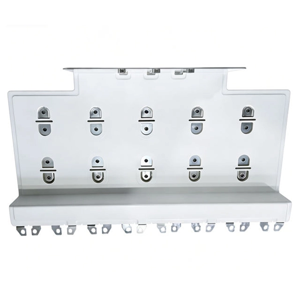
A Fiber optic cap type splice box is a protective enclosure designed to house and organize fiber optic splices. It typically features a dome or cap-style closure that provides a sealed environment for fiber joints, protecting them from external conditions. As fiber optic networks continue to expand across urban, rural, and industrial environments, the reliability of connection points becomes. The cap-type splice box is mainly designed for laying optical cables in overhead and tunnels. It does not meet the waterproof requirements of the regulations when used in direct-buried lines, but the moisture-proof effect in lines is better. According to regulations, the open type and other three. The types of optical cable splice boxes can be divided into cap-type optical cable joint boxes and horizontal optical cable joint boxes according to the shape and structure. According to. Grandway's fiber optic closure provides a high density wall mounted or pole mounted solution for next generation networks, which aims to provide and manage fiber splitters in a limited space. It is designed for FTTH (Fiber to the Home) or FTTB (Fiber to the Building) with protective housing for all. Briefly explain how fiber splice closures are critical for network protection and performance optimization. Introduce that choosing between dome (cap-style) and horizontal (in-line) closures depends on specific project requirements. Understanding Fiber Splice Closure Types 1.
[PDF]
Send us your information to receive a customized quote from our dedicated customer service team. •Compact benchtop instrument for all-in-one operation optic components quickly and accurately. The system has a or LED source for multi-mode applications. With a dual two wavelengths in less than 1 second. ILM-100 system comes integration into test systems. Insertion loss is measured by utilizing the built-in, stabilized LASER or LED source in combination with the precision optical power meter. Using the OP815, dual wavelength insertion loss (IL). Desktop Insertion Return Loss Tester with color screen has stable and reliable performance, which integrates stable light source, high-precision power meter, insertion loss meter and return loss meter into one multifunction instrument. Each SMLP5-5 Kit includes an OLS4 quad Optical Light Source and OPM5 Optical Power Meter. OLS4 is an integrated two-port LED (850 and 1300nm) and laser (1310 and 1550nm).
[PDF]

ITU & IEC allow 0. 75 dB loss per mated pair. Splitter loss values are "Typical" and include a connector in and out. These values are approximate and should not be exceeded by more than 1-1. 5 dB, which could indicate dirty connectors, bad splices, or. ITU & IEC allow 0. These are known as passive optical splitters, and they perform the function. Let's start with the simplest part: the ideal, theoretical loss caused purely by dividing the light equally among N paths. This is often called Distribution Loss or Ideal Split Loss. Understanding the types of splitters, their impact on network performance, and how to measure their losses ensures high-quality network operation and facilitates optimal splitter selection based on. Use 2×N when two inputs feed the same distribution stage. Common values: 2, 4, 8, 16, 32, 64. Wavelength is recorded in outputs for documentation. 5 dB depending on splitter type. Fusion splices often plan around 0. Optional: patch. Excess loss is the ratio of the optical power launched at the input port of the splitter to the total optical power measured from all output ports. It assures that the total output is never as high as the input. Components, such as fiber cables, splitters, and switches, introduce attenuation. The maximum allowable distance between a transmitting laser and receiver is based upon.
[PDF]
Find Prefabricated Telecom Shelter manufacturers, suppliers, dealers & latest prices from top companies in India. We are the first Indian company to provide 'Ready to Erect' Telecom Shelters in India with in-house Design, Engineering, Manufacturing and Erection / Installation capability all across India for efficient and cost effective operations of telecom equipment. (Dust Weather proof Insulated Cabin for. Prominent & Leading Manufacturer from Greater Noida, we offer portable prefabricated shelters and puf insulated telecom shelter. Our broad scope of pre-assembled covers incorporates a wide exhibit of Portable Telecom Shelters. Designed for rapid deployment and exceptional durability, our portable shelters are ideal for various applications, including the telecom and railway. Leading Manufacturer of prefabricated telecom shelters from Faridabad. Constructed with durable materials, these shelters ensure reliable performance.
[PDF]

Insertion loss tells you how much weaker the signal becomes after passing through the splitter. Let's say you have a laser output at 0 dBm (which is 1 milliwatt of optical power). If you use a 1×8 splitter with ~10. 5 dB of insertion loss, the power at each output would be: 0 dBm – 10. 5. Enter excess loss from the splitter datasheet for your wavelength. Add connector and splice quantities with realistic planning losses. Include any additional component losses and an engineering margin. Enable power budget to estimate received power and margin. Press Calculate to show results above. Understanding optical splitter loss isn't just about plugging numbers into a calculator. It's about knowing what factors contribute to that loss, how manufacturers specify it, and how it impacts the overall performance and reach of your network. Ignore it, and you might find your signal too weak to. Optical insertion loss refers to the signal loss resulting from the insertion of components such as connectors or splices in an optical fiber system. Common ratios: For cascades, add losses and validate margin using the Optical Budget tool. This Fiber Optic Splitter Insertion Loss is the splitter devices loss, Considering fiber connectors or connectors+adapter insertion loss in LGX, The fiber splitter IL would be a little bigger. To make clear the basic ftth fiber splitter loss in performance, You can refer to the below loss chart.
[PDF]

The most common fiber splice closure sealing methods include heat-shrink, mechanical, and gel-based sealing. While they all share the goal of isolating external factors, they achieve this in different ways. Gel seals utilize a soft gel material that adheres tightly to the cable. Another type of closure is a hybrid of splices and a patch panel. These are often used with fiber to the home (FTTH) networks where drop cables to individual subscribers are factory made preterminated cables and just require plugging in connectors - no splicing required. Here is two examples of. Fiber optic closures protect and organize cable splices, ensuring long-term stability in both outdoor and indoor networks. This guide explains their functions, types, and selection criteria, while showing how FiberMania's OEM customization helps achieve higher reliability and efficiency in modern. In modern FTTx and PON networks, fiber optic splice closures are the enclosures that protect fiber splice points from moisture, dust, and physical stress. Installing a fiber optic splice closure efficiently and effectively requires attention to detail and. 1 Sealing of the fiber optic splice closure (1) Clean the sealing groove around the joint box with alcohol cotton/wipes. (2) Insert the sealing strip into the sealing groove of the lower half of the joint box. This guide is written to provide a complete and engineering-oriented understanding of fiber optic splice closures—from basic concepts and.
[PDF]

Splice Diagrams or Matrices capture an electric or optical network inside a location – documenting cables, ported equipment, and connections. Splices are fiber-to-fiber, port-to-fiber and port-to-port. Fiber optic cable splicing involves joining two fiber optic cables together. Another method of connecting optical fibers is termination or connectorization, which consists of processing the end of a fiber optic bundle so that it can be connected to other fibers or devices through fiber optic. In this guide, we cover the basics of fiber optic splicing, how to perform splicing using two different methods, and finally some best practices to perform good fiber splicing. Ensure Your Splicing Tools are Clean – #2. Use and Maintain Your. What to show on a network diagram? Fiber optic network diagrams represent the architecture and connectivity of fiber optic systems, and their design philosophy integrates technical, functional, and conceptual aspects. The diagrams abstract complex details of fiber optic systems to make them. This Geoschematics drawing remains easy to read despite containing more than 2000 fibers and 500 splices. All students and instructors must wear safety glasses in this lab. It is copyrighted by the FOA and may not be distributed without FOA permission. This VHO covers similar material to the videos on YouTube. The lab manual has several.
[PDF]

Learn how to splice fiber optic cable using fusion splicing with this complete step-by-step guide. Includes tools, best practices, loss standards (ITU-T G. 652), cost analysis, and FAQs for network engineers and installers. Splicing fiber optic cable is an extremely important phase for making dependable, high-speed communication infrastructures. Regardless of the type of fiber network you're deploying, be it for telecom, enterprise data centers, or smart city infrastructure, fusion splicing provides the benefits of. This is where fiber optic cable splicing—the process of creating a permanent, high-performance join between two fiber ends—becomes critical. For network managers and technicians, a poor splice can lead to significant signal degradation, network downtime, and costly troubleshooting. At Turn-Key. Think of a fiber optic cable splice as the seamless stitching that keeps data flowing through the delicate threads of a network—like a master tailor joining fabric with precision. What is Fiber Optic Splicing and Why is it Needed? – #1. Discover how to efficiently use sleeves and the heat. The answer lies in splicing, both fusion and mechanical. In this comprehensive guide, we will delve into when.
[PDF]
This step by step fiber cutting guide shows you the correct tools and techniques for fiber opt. Executive Summary: A fiber optic pigtail is one of the most commonly specified yet least understood components in structured cabling. Get the wrong connector type, the wrong polish, or skip proper fusion splicing technique—and you're looking at elevated signal loss, increased back reflection, and a. Splicing thick cables correctly is essential to ensure efficient and safe transmission of electrical current. Improper splicing can cause a number of problems, such as loss of power, equipment damage, fire risk, and even personal injury. Regardless of the type of fiber network you're deploying, be it for telecom, enterprise data centers, or smart city infrastructure, fusion splicing provides the benefits of. Think of a fiber optic cable splice as the seamless stitching that keeps data flowing through the delicate threads of a network—like a master tailor joining fabric with precision. Whether repairing a broken cable or extending a fiber run, fiber optic splicing ensures light signals travel. This guide reveals the secrets to fusion splicing with little fluff—just proven, straightforward techniques refined from years of work in the field. The guide provides the complete workflow, covering safety precautions, tool selection, fiber preparation, fusion operation, quality control, and.
[PDF]
This splice case protect fiber optic cables and juction from outside plant environment damage. They are made of reinforced ABS or PC plastic, which has high strength and corrosion resistance. In addition, the splice enclosures are all hermetically sealing structure, waterproof and. Standard polycarbonate (PC) or Glassfibre reinforced (PC+GLAS) PP ABS (Acrylnitrile-butadiene -styrene) Slightly lower UV resistance compared with PC. Recommended for outdoor use if protected against weather influences GRP – GLASS FIBRE REINFORCED POLYESTER Polycarbonate and ABS enclosure materials. The fiber optic splice closure is a closed structure used for splicing, protecting and managing optical fibers. Its material selection is crucial to ensure the quality and service life of the fiber optic splice closure. These boxes are well suited as optical cable splice collection points for DAS (Distributed Antenna Systems), MTU (Multi-Tenant Unit) commercial business applications, and MDU (Multi-Dwelling Unit). It is a reentry box which is made of PC or PP material. The shells and the base are sealed with silicone gum. This product can be re-entered and used again after it is opened. Typically selected for high-density OSP splicing and branching. What is the basic structure of Fiber Optic Splice Closure? The basic structure of Fiber Optic Splice Closure includes the box body, box components, sealing ring, and lock buckle.
[PDF]

In this guide, we'll walk you through the entire process of preparing fiber optic cable for splicing and termination to fiber connectors. We'll explore the necessary tools, safety precautions, and step-by-step procedures for cable connectors, mechanical and fusion. At the heart of any robust fiber optic network lies a crucial process: Preparing a fiber cable for termination of a connector or splice. Two types of splices are used in fiber optic cabling one is Mechanical the other is Fusion. Whether you're installing a new network, expanding an existing one, or. Splicing fiber optic cable is an extremely important phase for making dependable, high-speed communication infrastructures. Regardless of the type of fiber network you're deploying, be it for telecom, enterprise data centers, or smart city infrastructure, fusion splicing provides the benefits of. Think of a fiber optic cable splice as the seamless stitching that keeps data flowing through the delicate threads of a network—like a master tailor joining fabric with precision. This article explains when. We terminate fiber optic cable two ways - with connectors that can mate two fibers to create a temporary joint and/or connect the fiber to a piece of network gear or with splices which create a permanent joint between the two fibers. These terminations must be of the right style, installed in a. So in essence, fiber optic splicing is a process used to join two separate fiber optic cables together.
[PDF]

