This chapter presents the development of the Energy Internet throughout the history as an evolutionary solution based on modern technological development and needs, with the respect of its architecture, key features, and key concepts, such as energy router, prosumer, and virtual. This chapter presents the development of the Energy Internet throughout the history as an evolutionary solution based on modern technological development and needs, with the respect of its architecture, key features, and key concepts, such as energy router, prosumer, and virtual. Energy Internet, a futuristic evolution of electricity system, is conceptualized as an energy sharing network. The. ITM University Gwalior, India. coordinating and controlling the many parts of a system, whether they are locally located or geographically dispersed. The study wraps up by outlining the most pressing problems that will need to be solved in order to implement an.
[PDF]

A Fiber optic cap type splice box is a protective enclosure designed to house and organize fiber optic splices. It typically features a dome or cap-style closure that provides a sealed environment for fiber joints, protecting them from external conditions. As fiber optic networks continue to expand across urban, rural, and industrial environments, the reliability of connection points becomes. The cap-type splice box is mainly designed for laying optical cables in overhead and tunnels. It does not meet the waterproof requirements of the regulations when used in direct-buried lines, but the moisture-proof effect in lines is better. According to regulations, the open type and other three. The types of optical cable splice boxes can be divided into cap-type optical cable joint boxes and horizontal optical cable joint boxes according to the shape and structure. According to. Grandway's fiber optic closure provides a high density wall mounted or pole mounted solution for next generation networks, which aims to provide and manage fiber splitters in a limited space. It is designed for FTTH (Fiber to the Home) or FTTB (Fiber to the Building) with protective housing for all. Briefly explain how fiber splice closures are critical for network protection and performance optimization. Introduce that choosing between dome (cap-style) and horizontal (in-line) closures depends on specific project requirements. Understanding Fiber Splice Closure Types 1.
[PDF]

ITU & IEC allow 0. 75 dB loss per mated pair. Splitter loss values are "Typical" and include a connector in and out. These values are approximate and should not be exceeded by more than 1-1. 5 dB, which could indicate dirty connectors, bad splices, or. ITU & IEC allow 0. These are known as passive optical splitters, and they perform the function. Let's start with the simplest part: the ideal, theoretical loss caused purely by dividing the light equally among N paths. This is often called Distribution Loss or Ideal Split Loss. Understanding the types of splitters, their impact on network performance, and how to measure their losses ensures high-quality network operation and facilitates optimal splitter selection based on. Use 2×N when two inputs feed the same distribution stage. Common values: 2, 4, 8, 16, 32, 64. Wavelength is recorded in outputs for documentation. 5 dB depending on splitter type. Fusion splices often plan around 0. Optional: patch. Excess loss is the ratio of the optical power launched at the input port of the splitter to the total optical power measured from all output ports. It assures that the total output is never as high as the input. Components, such as fiber cables, splitters, and switches, introduce attenuation. The maximum allowable distance between a transmitting laser and receiver is based upon.
[PDF]
Find Prefabricated Telecom Shelter manufacturers, suppliers, dealers & latest prices from top companies in India. We are the first Indian company to provide 'Ready to Erect' Telecom Shelters in India with in-house Design, Engineering, Manufacturing and Erection / Installation capability all across India for efficient and cost effective operations of telecom equipment. (Dust Weather proof Insulated Cabin for. Prominent & Leading Manufacturer from Greater Noida, we offer portable prefabricated shelters and puf insulated telecom shelter. Our broad scope of pre-assembled covers incorporates a wide exhibit of Portable Telecom Shelters. Designed for rapid deployment and exceptional durability, our portable shelters are ideal for various applications, including the telecom and railway. Leading Manufacturer of prefabricated telecom shelters from Faridabad. Constructed with durable materials, these shelters ensure reliable performance.
[PDF]

Insertion loss tells you how much weaker the signal becomes after passing through the splitter. Let's say you have a laser output at 0 dBm (which is 1 milliwatt of optical power). If you use a 1×8 splitter with ~10. 5 dB of insertion loss, the power at each output would be: 0 dBm – 10. 5. Enter excess loss from the splitter datasheet for your wavelength. Add connector and splice quantities with realistic planning losses. Include any additional component losses and an engineering margin. Enable power budget to estimate received power and margin. Press Calculate to show results above. Understanding optical splitter loss isn't just about plugging numbers into a calculator. It's about knowing what factors contribute to that loss, how manufacturers specify it, and how it impacts the overall performance and reach of your network. Ignore it, and you might find your signal too weak to. Optical insertion loss refers to the signal loss resulting from the insertion of components such as connectors or splices in an optical fiber system. Common ratios: For cascades, add losses and validate margin using the Optical Budget tool. This Fiber Optic Splitter Insertion Loss is the splitter devices loss, Considering fiber connectors or connectors+adapter insertion loss in LGX, The fiber splitter IL would be a little bigger. To make clear the basic ftth fiber splitter loss in performance, You can refer to the below loss chart.
[PDF]

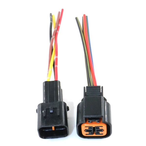
Just count the number wire leads coming from the connector and scroll to the section with that number. Executive Summary: A fiber optic pigtail is one of the most commonly specified yet least understood components in structured cabling. Get the wrong connector type, the wrong polish, or skip proper fusion splicing technique—and you're looking at elevated signal loss, increased back reflection, and a. Terminal Release Tools RTTP #s: NUD900-001, NUD900-002, NUD900-003 and NUD105-R025E Flex Probe Kit are available through RTTP. 2ND GENERATION - EXPANDED TO INCLUDE 8 AWG APPLICATIONS! Ford has identified through testing and engineering analysis, the optimal repair procedure for solderless wire. It includes an identification guide with images of various connectors and kits, highlighting their use in vehicle electrical repairs. The document details specific toolkits such as the Ford Flex Probe Kit and the Wire Splice Tool Kit, designed for repairing electrical wiring harnesses. Match the connector in the picture. They contain 5 uninsulated butt splices, 5 pieces of dual wall adhesive-lined heat shrinkable tubing, and the new instruction sheet detailing the approved wire splice procedure as defined by Ford Motor Company. Expanded wire gauge applications for these splices can be found in Technical Service.
[PDF]

This step-by-step fiber optic cold splicing tutorial makes it easy for beginners and professionals. ✅ One-time splice success – no more trial & error ✅ Mini. Fiber optics is the fastest and one of the safest ways to transmit information online. Fiber optic strands are ultra-lightweight and about as thin as human hair, and yet, they have more than eight times the pulling tension of a copper wire. And because fiber optic cables carry light instead of. This guide explores everything about fiber optic cable splice —from fiber fusion splice basics to how to splice fiber cable step-by-step—covering tools, techniques, and practical tips. This process requires precision, patience, and a deep understanding of the delicate nature of optical fibers. Before any splicing can occur, whether it's mechanical or fusion. Optical fiber Lengjie is used for optical fiber butt optical fiber or optical fiber docking pigtail, which is equivalent to making a joint, (fiber docking pigtail refers to the butt joint between the optical fiber and the core of the pigtail, not the pigtail head mentioned by the former), used for. This guide will walk you through the complete process of fiber optic splicing—covering each step in detail so you can deliver a clean, professional splice every time. Before jumping into the physical steps, it's important to understand the two primary methods of fiber splicing: fusion splicing and.
[PDF]

Primary: The main distribution panel, supplies power from the transformer. Differences Between Primary, Secondary, and Tertiary Distribution Boxes Designed for construction or large-scale projects as a main distribution point. Built to meet specific safety and operational standards for temporary construction sites. Incorporates a complete protection system (e. A feeder usually begins with a feeder breaker at the distribution substation. Many feeders leave substation in a concrete ducts and are routed to a nearby pole. At this. The equipment selection depends on the specific power load requirements. These units help control and protect the electrical circuits that serve things like cabin lighting, entertainment, and climate control. The main goal is to keep the primary systems safe while making sure secondary. What Is a Distribution Box? Types, Uses & How to Choose A distribution box, also known as a power distribution box or electrical distribution box, is used to distribute electrical power safely to multiple circuits. It helps organize, protect, and control electrical connections in residential. The main role of a distribution boxes is to channel electric current from the main supply to different circuits within a building. It also helps keep the electricity supply safe by preventing issues like short circuits and overloads. Most distribution boxes contain circuit breakers or fuses that.
[PDF]

Protective relays are essential devices used in electrical power systems to detect faults and abnormal conditions, initiating corrective actions to prevent equipment damage and ensure system stability. These relays play a crucial role in the protection of transformers, generators, transmission. A protective relay is an intelligent device that senses abnormal electrical conditions, such as overcurrent, under-voltage, or frequency deviations. It initiates the operation of circuit breakers to isolate the affected section. This prevents damage to equipment, reduces downtime, and safeguards. Protective relays are critical components in power systems, providing essential protection for various elements such as generator sets, outgoing feeder and load networks, and incoming utility sources. It functions as a watchdog by constantly surveying multiple system components including voltage, current, frequency, and phase angle. It. Protective relays and devices have been developed over 100 years ago to provide “lastline”of defense for the electrical systems. They are intended to quickly identify a fault and isolate it so the balance of the system continue to run under normal conditions. The selection and applications of.
[PDF]

Price and other details may vary based on product size and color. Need help?. This splice enclosure is designed as a simple distribution box for indoor installation. It could be utilised in small building facility or as floor box. Ideal for FTTH networks. This splice enclosure is designed as a. The large single port SC duplex wall outlet serves as a termination point, designed to connect two optical fibers via pigtails in FTTH or FTTB applications. It is small &lightweight, and is typically wall-mounted, providing a convenient sc duplex outlet to connect fiber to an ONT. Internal. Check each product page for other buying options. Need help?. Fiber Optic Splice Enclosures are essential components for protecting fiber optic splices and ensuring safe, secure, and organized fiber management. These enclosures are designed to accommodate splice trays, manage fiber optic cables, and protect sensitive connections from environmental factors. Fiber Optic Splice and Joint Enclosure Box is a fiber management product typically used with outdoor fiber optical cables and underground fiber splice enclosure. Fiber splice enclosure box is used for. CommScope addresses these challenges with a comprehensive family of fiber splice closures that prioritize essential criteria: reliability, installability, flexibility, and speed of deployment. Trunk and Feeder Network Solutions: These closures are designed for robust performance in the backbone of.
[PDF]

Learn how to splice fiber optic cable using fusion splicing with this complete step-by-step guide. Includes tools, best practices, loss standards (ITU-T G. 652), cost analysis, and FAQs for network engineers and installers. Splicing fiber optic cable is an extremely important phase for making dependable, high-speed communication infrastructures. Regardless of the type of fiber network you're deploying, be it for telecom, enterprise data centers, or smart city infrastructure, fusion splicing provides the benefits of. This is where fiber optic cable splicing—the process of creating a permanent, high-performance join between two fiber ends—becomes critical. For network managers and technicians, a poor splice can lead to significant signal degradation, network downtime, and costly troubleshooting. At Turn-Key. Think of a fiber optic cable splice as the seamless stitching that keeps data flowing through the delicate threads of a network—like a master tailor joining fabric with precision. What is Fiber Optic Splicing and Why is it Needed? – #1. Discover how to efficiently use sleeves and the heat. The answer lies in splicing, both fusion and mechanical. In this comprehensive guide, we will delve into when.
[PDF]
This splice case protect fiber optic cables and juction from outside plant environment damage. They are made of reinforced ABS or PC plastic, which has high strength and corrosion resistance. In addition, the splice enclosures are all hermetically sealing structure, waterproof and. Standard polycarbonate (PC) or Glassfibre reinforced (PC+GLAS) PP ABS (Acrylnitrile-butadiene -styrene) Slightly lower UV resistance compared with PC. Recommended for outdoor use if protected against weather influences GRP – GLASS FIBRE REINFORCED POLYESTER Polycarbonate and ABS enclosure materials. The fiber optic splice closure is a closed structure used for splicing, protecting and managing optical fibers. Its material selection is crucial to ensure the quality and service life of the fiber optic splice closure. These boxes are well suited as optical cable splice collection points for DAS (Distributed Antenna Systems), MTU (Multi-Tenant Unit) commercial business applications, and MDU (Multi-Dwelling Unit). It is a reentry box which is made of PC or PP material. The shells and the base are sealed with silicone gum. This product can be re-entered and used again after it is opened. Typically selected for high-density OSP splicing and branching. What is the basic structure of Fiber Optic Splice Closure? The basic structure of Fiber Optic Splice Closure includes the box body, box components, sealing ring, and lock buckle.
[PDF]

In this guide, you will find a chronological description of the fusion splicing process, the principal technical standards, and answers to the real-life questions network engineers and procurement teams may have. In this guide, we cover the basics of fiber optic splicing, how to perform splicing using two different methods, and finally some best practices to perform good fiber splicing. What is Fiber Optic Splicing and Why is it Needed? – #1. Use and Maintain Your. This Geoschematics drawing remains easy to read despite containing more than 2000 fibers and 500 splices. Splice Diagrams or Matrices capture an electric or optical network inside a location – documenting cables, ported equipment, and connections. Splices are fiber-to-fiber, port-to-fiber and. This guide will walk you through the complete process of fiber optic splicing—covering each step in detail so you can deliver a clean, professional splice every time. Before jumping into the physical steps, it's important to understand the two primary methods of fiber splicing: fusion splicing and. Page 1 The FOSC 450 fiber optic splice closures use compressed-gel cable seals to environmentally seal fiber cable splice points. FOSC 450-ab-c-dd-e-fgh The maximum single splice capacity of the FOSC 450 B6 closure is a = Closure size 144 with 24 splices stored on six trays. Therefore, we will also touch on cost factors, risk management, and best practices in.
[PDF]

