The interface fc command displays the Fibre Channel (FC) interface view. Specifies the number of an FC interface. Devices on a storage area network (SAN) use FC interfaces to communicate and carry traffic. You can then perform. FC switches are required for applying for DESS devices of the common I/O (low latency), high I/O (low latency), or ultra-high I/O (low latency) types. An FC switch is a high-speed network transfer device that uses optical fibers as the media. It features high-speed transfer and strong. Get the latest official Huawei FC - Application Interface port (COM/LPT/Serial) drivers for Windows 11, 10, 8. Update drivers using the largest database. The good news is that HF now shows two ports in the COM dropdown and is recognized in Mobile Partner! The bad news is that reading still fails, no matter what port combo I specify, even modem port. These are the observations before/after setting AT^SFM=1. Thus we lost SD card as a recognized drive. Copyright © 1998-2026 Huawei Device Co. FCF functions as the access switch and connects the storage device Array through its uplink interfaces, and directly connects to ServerA through its downlink interface, as shown in Figure 2-35. ServerA connects to FCFA and FCFB to constitute dual-plane networking, ensuring network reliability.
[PDF]
FC used throughout all applications for Fibre Channel infrastructure and devices, including edge and ISL interconnects. Each speed maintains backward compatibility at least two previous generations (I.e., 32GFC backward compatible to 16GFC and 8GFC)OverviewFibre Channel (FC) is a high-speed data transfer protocol providing in-order, lossless delivery of raw block data. Fibre Channel is primarily used to connect to in (SAN) in co. When the technology was originally devised, it ran over optical fiber cables only and, as such, was called "Fiber Channel". Later, the ability to run over copper cabling was added to the specification. In order to avoid confu.
[PDF]
An optical module is a typically hot-pluggable optical transceiver used in high-bandwidth data communications applications. Optical modules typically have an electrical interface on the side that connects to the inside of the system and an optical interface on the side that connects to the outside world through a fiber optic cable. The form factor and electrical interface are often specified by an int. Electrical Interface TypesThere have been multiple variants of the electrical interface of optical modules that have been used over the years. The earliest forms of optical modules had an analog electrical interface. In the transmit dir. Many different forms of optical modulation and multiplexing have been employed in optical modules. The most common modulation technique historically has been or NRZ.
[PDF]

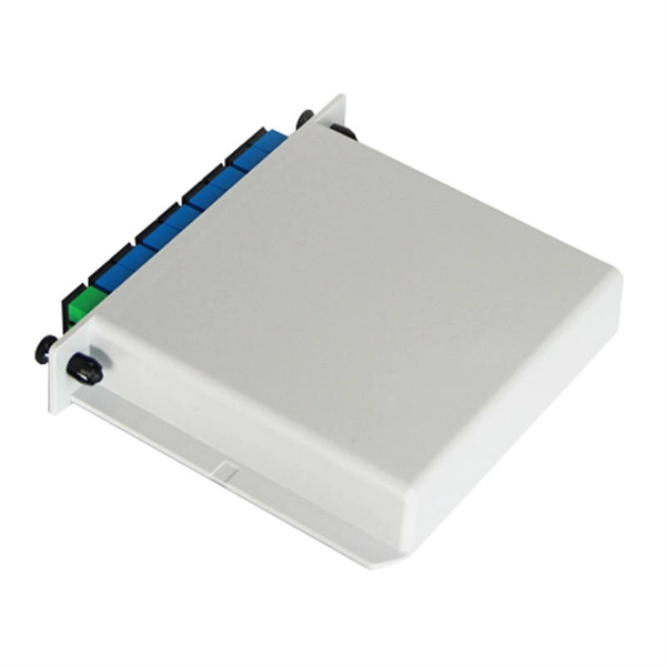
Yes, but the ideal solution is to use a two-way splitter at your ONT. One port is for the phone near the ONT, then use a phone extension cord to "back-feed" to the nearest interior phone jack. Then you can plug a phone into any other phone jack throughout the house and it'll just work. Centralized – A centralized split has one or more splitters together at a centralized location. Centralized splitting occurs often, but not always, in central ofices or. An optical splitter, also known as an optical fiber splitter or fiber optic splitter, is a passive device used to divide an optical signal into multiple outputs. They are primarily used in fiber optic networks to distribute signals from a single source to multiple destinations. This mechanism is. These unassuming devices enable a single optical signal to be divided into multiple paths, making them indispensable for sharing network resources efficiently—from residential FTTH (Fiber-to-the-Home) connections to large-scale telecom backbones. Conversely, it can also combine multiple signals into one. The fiber optic.
[PDF]

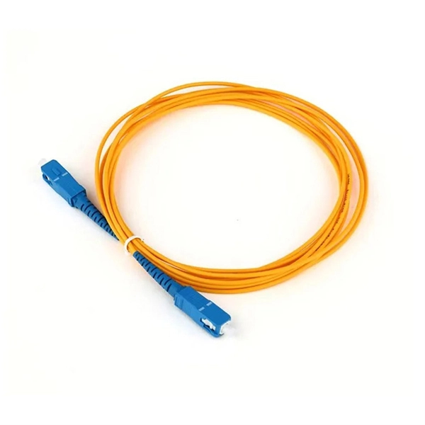
This guide will walk you through the most common fiber connector types, explaining their characteristics, advantages, and typical use cases. An optical fiber connector is a device used to link optical fibers, facilitating the efficient transmission of light signals. An optical fiber connector enables quicker connection and disconnection than splicing. Whether you're planning an FTTH deployment, upgrading a data center, or working in telecom infrastructure, this guide will help you make informed decisions. This guide provides a fully updated and industry-ready overview of LC fiber optics, explaining the origin and design of LC connectors, their key features, and the complete ecosystem of LC-based products used in modern networking. It covers LC connectors, LC patch cables, uniboot designs, armored. Fiber connector types LC, SC, FC, ST, MTP, and MPO are widely used in past and present. What are the differences between them? Who is the most popular one? Find the answer in the article. What is a Fiber Connector? The optical fiber connector is a kind of detachable passive optical component used. The answer often lies in tiny but mighty components called LC connectors. There have been many types of connectors developed for fiber cable. Single mode networks have used FC or SC.
[PDF]
Follow the described steps to factory reset an IBM Brocade switch running FOS 7. Run firmwarecleaninstall on each CP or switch After firmwarecleaninstall, all passwords, such as root, admin, factory and user are cleared (set to the default value). Before installing a new software version and RCF files, you must erase the current switch configuration and perform basic configuration. Log in to the switch as an administrator. The system is halted flushing ide devices: hda Power down. Display information about switches in the fabric. Display how long the switch is running, number of connected users and the system load for the past 1, 5 and 15 minutes. Display or set date and time (This is Readonly if NTP is. This video will demonstrate clear procedure of an interface and ASIC counters on Brocade B-Series Switches and Directors Welcome to Dell Technologies Connectrix Brocade How To Series. WARNING: This is a.
[PDF]

The FC/PC (Physical Contact) and FC/APC (Angled Physical Contact) fiber optic connectors are standardized under TIA EIA/TIA-604-4 and IEC 61754-13. ABSTRACT: This standard describes the point-to-point physical interface portions of Fibre Channel serial electrical and optical link variants that support the higher level Fibre Channel protocols includ-ing FC-FS, HIPPI, IPI, SCSI and others. This standard is recommended for new implementations but. Fiber connector types LC, SC, FC, ST, MTP, and MPO are widely used in past and present. What are the differences between them? Who is the most popular one? Find the answer in the article. What is a Fiber Connector? The optical fiber connector is a kind of detachable passive optical component used. An optical fiber connector is a device used to link optical fibers, facilitating the efficient transmission of light signals. An optical fiber connector enables quicker connection and disconnection than splicing. Unlike fiber splicing, which is permanent, connectors allow for easy connection and disconnection of cables, making them ideal for maintenance and flexibility in. Understanding fiber connector types—SC/APC, SC/PC, LC/UPC, LC/APC, ST/PC, FC/PC, and FC/APC—is essential for selecting the right interface for your application. Each type varies by shape, polish (APC, PC, or UPC), and return loss performance, which affect PC, UPC, and APC Polish Styles: What's the.
[PDF]