Unlike traditional metal-style reels, MARS is a lightweight, modular system constructed of an impact modified polymer that is easily transported. It is ideal for applications where cable needs to be deployed and reeled in quickly and stored efficiently. OCC's Modular Advanced Reel System (MARS ®), the industry's first lightweight cable deployment reel system, is designed specifically for the demanding needs of harsh-environment fiber optic installations. The dual take-ups are designed to work independently from line controls, therefore providing an easy adaptation and a fast plug & play installation to any line.
[PDF]

Attach a ground wire from one of the threaded studs (A) at the bottom of the housing, to the mounting plate (B). The ground resistance between all system parts shall be <. The correct connection method of Distribution box grounding wire mainly includes the following steps: 1. This position is the connection point of the grounding wire in the. The National Electrical Code (NEC) lists eight specific methods to make grounding and bonding connections in Sec. Failure to install these connections properly can result in shock, fire, or, most certainly, power quality problems. Let's take a look at each one in more detail. Listed pressure. Make the most of outdoor spaces with permanent, weathersafe power. Learn our complete installation process from start to finish. Watch our video to learn more. Securing the ground wire: Secure the grounding wire to the ground bar using a grounding screw or terminal. Each DISTRIBUTION BOX and controller must be grounded. On the US market, a 5. 26 mm 2 (10 AWG) ground wire must be used, and in all other markets a 6 mm 2 must be used. Grounding of the units: Attach a ground wire from one of. Learn how to install a distribution box safely and correctly. Covers wiring, placement, standards, and expert tips for a compliant setup. A distribution box is the heart of any electrical system. It takes the incoming power and safely distributes it to different circuits throughout your building.
[PDF]
You use a fiber distribution panel to keep fiber optic cables organized. This panel helps you manage cables in your network. The panel protects connections from dust and water. It also shields them from changes in temperature. With the growth of the fiber industry, a wide array of fiber optic patch panels have been developed to fit the many needs of these varying environments. If you already know what your project requires, check out our complete Fiber Patch Panel selection. What is a Fiber Patch Panel? Fiber optic patch. A fiber patch panel is a mounted enclosure—either rack-mounted or wall-mounted—used to terminate, manage, and interconnect multiple fiber optic cables. It acts as a hub for organizing splices and patch cords, streamlining fiber management and preserving signal integrity. You use this device to connect and separate fiber cables. It lets you reach each fiber connection easily.
[PDF]

When it comes to testing fiber optic cables, a Visual Fault Locator (VFL) is an essential tool in your toolkit. A VFL is used to detect faults, breaks, or bends in fiber optic cables by emitting a bright red light that is visible even through the fiber's jacket. Let's dive into everything you need to know about mastering VFLs. It's a cost-effective and. Visual Fault Locator (VFL) testing is one of the most fundamental inspection methods used in FTTH, ODN, and data center environments. A VFL emits a visible red laser (typically 650 nm) that travels along the fiber core and leaks out at points of excessive loss, fiber breaks, or microbends. Although. The Fiber Visual Fault Locator Kit is an essential tool for network technicians and engineers; it provides an accurate and quick method of finding such problems as breaks, bends or faults that may affect the network's operation. It works by injecting a visible red laser light (usually in the 650nm wavelength) into the fiber. When the light encounters a fault, such as a break, bend, or bad splice, it leaks out of the fiber, making the. Conducting efficient, repeatable fiber optic cable certification requires an array of specialized test equipment: Optical Loss Test Set (OLTS) – Integrates adjustable light source and power meter for efficient, Tier-1 insertion loss testing. Visual Fault Locators – Handheld devices projecting.
[PDF]

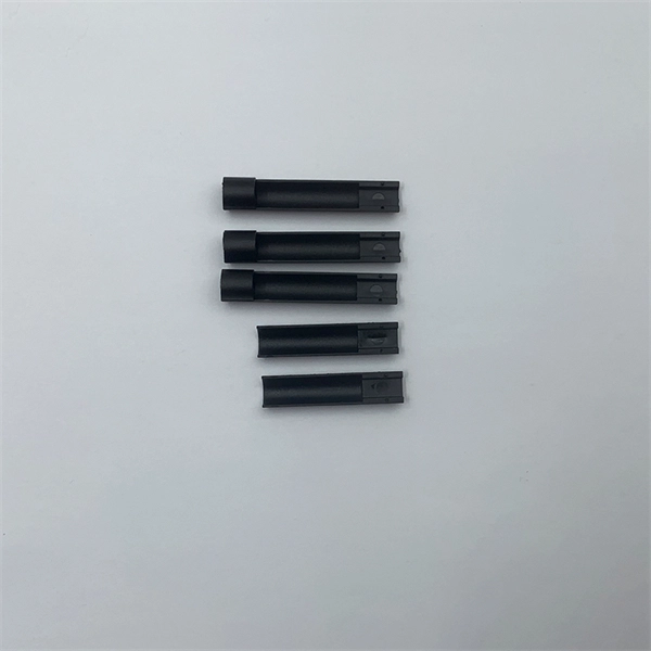
Although they may appear similar at first glance, singlemode and multimode fiber pigtails differ significantly in fiber structure, transmission performance, cost, and application suitability. Choosing the wrong type can lead to unnecessary signal loss, limited scalability, or. Fiber optic pigtails play a critical role in modern optical networks, serving as the interface between optical fibers and active or passive devices through fusion splicing. Among the various options available, singlemode fiber pigtails and multimode fiber pigtails are the two most widely used. Single-mode (SMF) and multi-mode fiber (MMF) use different core sizes, sources and wavelengths. These differences determine which transceivers work with which fiber and how far signals can travel. Understanding the compatibility constraints prevents costly downtime and troubleshooting. Single-mode. Understanding the differences between single-mode and multi-mode fiber pigtails is crucial for selecting the right type for data centers, telecommunications, FTTH (Fiber to the Home) installations, or enterprise networks. Choosing the right pigtail directly impacts signal transmission distance. So what's the cause of mix-using multimode and single-mode fiber? As we see, the optics applied in point-to-point interconnection are symmetrical. For instance, end A with a 10G SFP+ port houses a 10GBASE-SR SFP+ module.
[PDF]

FTTO is a hybrid network involving fibre optic cabling (pre-terminated or extractable cables) and copper twisted pair patch cords with 8P8C connectors. . It combines passive elements (fibre optic cabling, patch panels, splice boxes, connectors and standard copper 8P8C patch cords) and active mini-switches (called FTTO switches) to provide end devices with Gigabit Ethernet. FTTO involves centralised optical fibre cabling techniques to create a. About the Author : Clifford C. Walker has had a checkered career spanning from 14 years in the British Army, as a Control Technician, before leaving in 1979 and eventually entering the Computer Industry in 1981. His first few companies were associated with Main Frame Computer Installations for both. O) is a standard compliant and decentralised cabling concept for modern ofice environments. It combines the advant ges of highly eficient fiber optic technology with the flexibility of twisted pair cabling. Copper cable only comes to. FTTO highly concentrates the optical communications network for all office, especially for the central business districts (CBD). Get an highly integrated FTTO network solution today! FTTO refer to Fiber To The Office.
[PDF]
The Telecommunications Regulatory Authority of the Kingdom of Bahrain approves that the equipment listed below is in compliance with the Regulation on the Approval and Importation of Telecommunications Equipment (Public) and is allowed to be placed in the market of the Kingdom. FOXCONN INTERCONNECT. When selecting equipment for electrical installations within your building, we make it easy to find trusted, approved products. Choosing from EWA's Approved Equipment List ensures safe, high-quality performance and reliable systems that fully comply with all regulations. Below is the list of. Distribution Boards are designed and manufactured for indoor or outdoor application. The degree of protection is in accordance with IEC 60529. Ascon Control WLL is Bahrain's one of the most reliable manufacturer of Control Panels, Distribution Boards, Substations, Sub Main Switchboards. BHD 29. BSLI guarantees its customers fast, personalized service, quality components, and custom-designed equipment at competitive prices. OUR manufacturing and engineering capabilities have expanded to.
[PDF]
This document outlines the key requirements for cable tray layout, installation, and fireproofing in industrial and commercial environments. Route Planning and Layout Principles. Provides technical requirements concerning the construction, testing, and performance of metal cable tray systems. It is the first joint effort of NEMA and CSA International to put in one place standards for metal trays per both NEMA and CSA methods. Addresses shipping. Method Statement installation of Cable Trays and Ladders - Planning Engineer FZE. Whether you're designing a new. Below is the detailed cable tray installation method statement not only for cable tray but also applicable for GI ladder and trunking for indoor and outdoor applications and in service rooms like pump rooms, electrical rooms and plant rooms etc. All materials intended for cable tray, ladder and. Cable tray installation must comply with specific technical standards to ensure electrical safety, system reliability, and long-term maintainability. The mechanical and electrical characteristics, tests, certifications, overall quality management, recommendations mentioned in this technical guide only apply to our own cable management ranges and cannot under any circumstances be transpos regulations which.
[PDF]

This blog article entry considers the merits of choosing which of various low loss RF coaxial cables to use for IoT, LTE or LORA wireless applications where an external antenna is used to connect to router, gateway or terminal. The choice looks deceptively simple—pick a length, screw it on—but RF engineers know the truth: every extra meter quietly eats away at your link budget, especially once you cross 2 GHz. It's not just about length; the cable type, connector quality, and even mounting environment make a measurable. Audio generated by DropInBlog's Blog Voice AI™ may have slight pronunciation nuances. In this article, we will consider cables such as RG174, RG58, RF195. The cheap connectors have inferior dielectric between the poles as well as poorer grades of metal. The dielectric won't handle high power (KW range) as well and the center pin can more easily shift causing impedance problems if they are moved frequently. RF connectors are usually used with coaxial cables. They are designed to maintain the shielding that the coaxial design offers. The better and newer. Besides the wide range of RF connectors, Telegärtner also provides a considerable range of suitable coaxial low loss cables. Using this one-stop shopping option at Telegärtner makes your purchasing process even more efficient. The main use of low loss cables are all kinds of wireless applications.
[PDF]
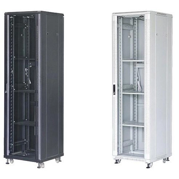
5G outdoor cabinets, also referred to as 5G cabinets or 5G enclosures, are boxes designed to house and protect the electrical equipment to support 5G-LTE technology. Made of metals, plastics or a combin.
[PDF]

Understanding how to properly place and use an optical splitter is essential for optimizing signal quality and ensuring seamless data transmission. Let's explore the best practices for deploying this crucial component. What is An Optical Splitter?. A fiber optic splitter is a passive optical component that divides a single incoming optical signal into two or more outgoing signals, or combines multiple incoming signals into one. Unlike active devices (which require power), splitters operate without electricity, relying solely on the physics of. Where splitters are placed in the network can make significant impacts on fiber counts, network cost and deployment time and operational steps, such as customer onboarding and maintenance. One important note is that splitting architectures should be seen as tools that can be mixed and matched to. In the realm of optical communication networks, the optical splitter serves a vital role in dividing and distributing optical signals efficiently. You use optical couplers and splitters to split or join signals in fiber networks. These devices help you control light signals well. You can also use them to join light from. This guide will demystify this pivotal passive device, exploring its types, working principles, and how it seamlessly integrates with optical transceivers to bring high-speed internet to your doorstep.
[PDF]
Single mode and multimode fiber optic cables are two different types of fiber optic cable aimed at different use cases. Single mode cables are typically made with a single strand of glass at their core, leading to a n.
[PDF]

As a key parameter for evaluating data transmission accuracy, the bit error rate directly determines the reliability and stability of communication systems. This article delves into the fundamentals and testing methods of the bit error rate. A bit error occurs when a single binary digit is flipped during transmission, meaning a logical '0' is mistakenly interpreted as a '1' by the receiver, or a '1' is read as a '0'. Through the interpretation of actual test reports, it. BER is calculated by comparing the transmitted sequence of bits to the received bits and then counting the number of errors. The ratio of how many bits received in error over the total number of bits received is the BER. This ratio is affected by many factors including: signal to noise, distortion. Bit Error Rate (BER) is a crucial metric in signal processing and communication systems, measuring the frequency of errors in data transmission. It is defined as the ratio of the number of bits received in error to the total number of bits transmitted over a communication channel during a specified. In the fast-paced world of digital communication—where billions of bits travel through wires, fibres and wireless links every second—the concept of bit error rate (BER) is both fundamental and profound. It involves measuring the rate at which errors occur in a transmitted bitstream compared to the expected bitstream at the receiver end. The BER measurement helps in assessing the quality.
[PDF]


