Learn how to physically set up an Industrial Switch in just a few minutes!This video covers:✔ Mounting the switch✔ Connecting power✔ Plugging in Ethernet cab. to this Installation Standards shall be approved and be published by the URA. The URA shall notify each Service Provider of the amendment proved at least twenty (20) Business Days prior to the revision taking effect. The revision shall take effect with this Installation Standards deemed to be. Purpose The purpose of these Installation Standards is to set the technical requirements and standards for the design and installation of electrical assets in the Republic of Maldives. The Installation Standards will develop the following aspects: Standards for LV Electrical. The Electrical Work shall be carried out strictly in accordance with the standard specifications and shall also conform to the requirements of Maldives Energy Authority. All materials to be used in the Works shall be of standard make and shall bear the certification marks of local authorities. Having experience for over 12+ years we provide a wide range of electrical engineering services in Maldives at a very affordable rate. The ultimate aim of our company is to provide solution based services that optimize and integrate all the components that are associated with the power systems.
[PDF]
The state imposes a number of restrictions and requirements on the activities of foreign agents. As of March 2021, foreign agents in Russia are divided into three groups, which were defined by law in different years: • Non-profit organizations-foreign agents - since 2012. • Media-foreign agents - since 2017.
[PDF]

Mechanical Optical Switches: Switching times typically range from 1-10ms, suitable for long-distance transmission scenarios where latency is not critical (such as backbone network protection switching). Solid-State Optical Switches: Based on thermooptic or electrooptic effects, response. We lead the industry in optical switch technology, delivering the lowest insertion loss (0. 2 dB), fastest switching speed (10 ns), broadest wavelength range (300–2400 nm), widest fiber compatibility, highest optical power handling (50 W), and space-qualified reliability. Backed by over 25 years of. Use this optical switches buying guide to compare major types, define selection criteria, and find suppliers: Professional purchasing of high-value photonics products is a substantial responsibility, where a structured decision-making process is essential. RP Photonics offers a lot of help: Get. This document is a troubleshooting and selection guide for common optical switch failures, compiled based on over 500 field cases. These switches are built on proven, reliable optomechanical technology that has seen more than 30 years of successful operation. Each. The POLATIS ® Series 7000 384x384 all-optical circuit switch is designed to meet the most demanding applications with exceptionally low optical loss, compact size, and fast switching speeds. With support for Software-Defined Networks (SDNs) via embedded NETCONF and RESTCONF control interfaces, the.
[PDF]

In this article, we will look at a variety of different Ethernet interface types: RJ45, fiber-optic, the common industrial M12 connection, and SFP, which stands for 'small form-factor pluggable. ' The RJ45 port is one of the most common Ethernet setups and is compatible with. Industrial Ethernet switches are the backbone of communication in industries such as transportation, energy, and manufacturing. A vital component of these switches is their interfaces, which facilitate seamless data transmission across a network. This article introduces the types, forms, and. This handy selection guide in PDF format provides you with a comprehensive overview of the extensive range of HARTING products available in the broad market of Industrial Ethernet Connectivity. They are robust, impact-resistant and temperature-resistant. All products fulfill the highest requirements for reliable and flexible industrial Ethernet communication. Unmanaged switches are the simplest active network. WAGO's switch portfolio provides scalable Ethernet network infrastructure with excellent electrical and mechanical performance. These rugged devices are designed for industrial use and are fully compatible with IEEE 802. The WAGO PoE Splitter (Item Number. Ethernet switches can use four different types of connections: RJ45, fiber, M12, and SFP. Understanding the difference can help with network troubleshooting, design, or alteration.
[PDF]
With 14 top 10G Ethernet switches for 2025, discover the best options to elevate your high-speed network—continue reading to find your ideal match. The global market for 10 Gigabit Switch was estimated to be worth US$ million in 2024 and is forecast to a readjusted size of US$ million by 2031 with a CAGR of %during the forecast period 2025-2031. A 10 Gigabit switch is a network switch that supports data transfer rates of up to 10 gigabits per. In this guide, we've tested and reviewed the best 10Gb switches to help you make an informed decision. From performance to features and value for money, we will walk you through everything you need to know to pick the ideal 10Gb switch for your needs. Check out the thorough review of the best 10Gb. Advantech's industrial Ethernet solutions provide an abundance of product options including managed and unmanaged switches, Gigabit Ethernet switches, PoE switches (IEEE 802. 3at), protocol switches, EN50155 and IEC61850-3-certified switches, and SFP modules with rackmount and. Moxa provides a wide range of industrial Ethernet switches that feature industrial-grade reliability, network redundancy, strengthened security, easy management, and competitive price-to-performance ratios. These 10G industrial switches deliver ultra-fast connectivity with support for 10Gbps data rates, ensuring seamless communication for bandwidth-intensive applications.
[PDF]
Being managed or unmanaged in a Power over Ethernet switch is the part that defines whether or not you want to take control of your PoE switch and be responsible for everything that occurs in your net.
[PDF]

Mount individual circuit breakers in the designated positions within the distribution box. Each breaker should match the current rating and type required for its specific circuit. Ensure proper connection to the busbars and secure mounting to prevent loosening over time. When opening the distribution box, several different brands of circuit breakers are installed inside. It seems that the sizes match and the installation is fine, and this. The feeder amp rating is sized based on the sum of the amp rating of the largest branch protective device plus the full-load currents of the other loads. This value is added to the full load currents of the. Finding the right circuit breaker for your electrical panel is crucial to ensure safety, performance, and code compliance. Not all breakers are interchangeable across different panel brands – each manufacturer designs its breakers and panels as a matched system. Using a breaker that isn't made or. In industrial power distribution systems, cable distribution boxes (also known as power distributor boxes, distribution electrical boxes, or electrical power distribution boxes) are the core hub of power transmission, branching, and protection. You lower the chance of circuits getting too hot or overloaded when you pick the right box for your needs. A single circuit breaker installation mistake can cost your facility thousands in downtime, equipment damage, or worse—put lives at risk.
[PDF]

This video shows real on-site footage of electrical installation, demonstrating safe and standardized wiring methods used by professionals. The National Electrical Code (NEC) Section 700. 10 provides critical guidelines for the wiring of emergency systems. These systems ensure continued operation during power outages, protecting lives and maintaining functionality in key buildings. This guide breaks down the essential requirements of. Emergency system circuits supply power to critical life safety loads such as emergency lighting, fire alarm systems, fire pumps, smoke control systems, and essential communication and control circuits. Correct wiring design for emergency system circuits is essential to maintain power integrity. The general rule in 700. 10 (B) is to keep wiring from an emergency source or emergency source distribution overcurrent device to the emergency loads entirely separate from all other wiring and equipment, unless otherwise permitted in 700. 10 (B) (1) through (5). 12) of the interruption of the normal electrical supply.
[PDF]

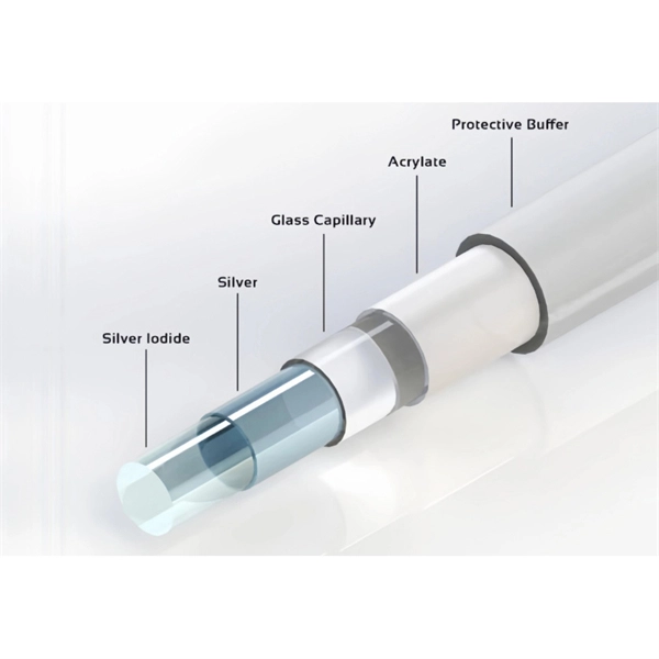
This video goes over common types of connectors, their respective adapters, and how to properly connect and disconnect them. For your safety, it is always advised to follow proper fiber optic handling techniques and utilize the correct protective gear when performing. Plan your outdoor fiber installation carefully by surveying the site, choosing the right cable type, and following FOA and OSP standards to ensure reliability. Select the best installation method—direct burial, aerial, conduit, or underwater—based on your environment and future network needs. Use. Proper connection of fiber optic cables is essential to harness these benefits fully, as even minor errors can lead to significant performance issues like signal loss. more Are you interested in seeing how fiber optic connectors get. The Fiber Optic Association, Inc. (FOA) was founded in 1995 to help develop the workforce to build the fiber optic networks to support a rapid expansion in communications and the Internet. The charter of the FOA was to promote professionalism in fiber optics through education, certification, and. Outdoor OPT Fiber Optic connectors integrate common fiber interfaces (SC, duplex LC, MPO) inside a sealed, rugged housing for harsh environments. Each assembly houses a standard indoor connector (SC, LC, or MPO) within a waterproof shell. At its core, the optical fibers are enclosed within protective layers that are resistant to pressure, water, and ultraviolet radiation.
[PDF]

This guide will explain their functions, discuss the role of single-mode LC connectors in modern fiber optic systems, and present the logic for their adoption on a broader scale. Proper connection of fiber optic cables is essential to harness these benefits fully, as even minor errors can lead to significant performance issues like signal loss. This article will guide you through the necessary tools, materials, and methods on how to connect fiber optic cables effectively. Fiber optic internet delivers blazing-fast speeds and reliable connectivity, making it a top choice for modern homes and businesses. In this guide, we'll walk you through how to. In this article, we'll explain how to connect multiple Ethernet switches using fiber optic cables and the equipment required for this to work. Network topology refers to the way in which the links and nodes of a network are arranged in relation to each other. There are also fiber-to-fiber versions that translate between different fiber types, wavelengths, or distances. Common families support 10/100/1000 Ethernet and. This is where single-mode fiber optics comes in. Single-mode fiber is being viewed as the backbone of enterprise connections, and it is used to facilitate all 400G solutions and real-time AI solutions/applications, due to its ability to transmit data over long distances with minimal signal loss.
[PDF]

These installation instructions provide overview and specification information for small form-factor pluggable (SFP/ SFP+/SFP28) modules, as well as instructions for installing and removing the modules. SFP (Small Form-factor Pluggable) transceivers are essential components in modern fiber optic networks, enabling network devices such as switches, routers, and servers to transmit and receive data over optical fiber. By converting electrical signals into optical signals—and vice versa—SFP. Gigabit single-mode fiber optic module Common parameters of optical modules 1. Center wavelength 1) 850nm (MM, multi-mode, low cost, but short transmission distance, usually only 500M); 2) 1310nm (SM, single mode, large loss during transmission, small dispersion, generally used for transmission. As a leading provider of fiber optic solutions, Weunion offers a wide range of SFP-compatible products, including optical transceivers, DAC/AOC cables, LC patch cords, and MPO/MTP assemblies. While they may appear to be simple plug-in transceivers, SFP modules are precision-engineered devices that directly influence network. o In optical modules, "core" refers to the light-transmitting channel in the fiber. A 1-core module uses a single fiber core for data transmission, while a 2-core module uses two cores. o Think of a highway. A 1-core fiber is like a single-lane road—only one car (or data signal) can travel at a.
[PDF]

Fiber optic network design (896. 83 KB). Welcome to the Corning LANscape® Solutions Product Drawings Resource Center, your complete source for our optical hardware component drawings. The two-dimensional and isometric hardware products drawings are available in PDF (Adobe® Acrobat®), DXF (AutoCAD®), VSS (Visio® Stencil) formats, and. I'm wanting to create documentation for a control fiber optic network. I'm needing symbols for common fiber optic components, cables, connectors, backbone ports, etc. Can anyone help me out? Some examples of a diagram would also help. 10-27-2018 01:41 AM Do you know if there's some symbol standard. Search by part number or description such as CAT5, CAT6, OSP, etc. Sort by any of the table headers. Use the drop down menu to filter by product category and type. Sort by any. Download CAD block in DWG. Free CAD and BIM blocks library - content for AutoCAD, AutoCAD LT, Revit, Inventor, Fusion 360 and other 2D and 3D CAD applications by Autodesk. CAD blocks and files can be downloaded in the formats DWG, RFA, IPT, F3D. You can exchange useful blocks and symbols with other CAD and BIM users.
[PDF]

Mainly 9steps: Step 1: cut cable with cutting machines in lengths Step 2: put the connector spare parts on the cable Step 3: Strip cable jacket, coating till bare fiber, and make all parts in ready Step 4: Insert fiber into ferrule, glue dispenser and heat oven Step 5:. Mainly 9steps: Step 1: cut cable with cutting machines in lengths Step 2: put the connector spare parts on the cable Step 3: Strip cable jacket, coating till bare fiber, and make all parts in ready Step 4: Insert fiber into ferrule, glue dispenser and heat oven Step 5:. Learn how to make a fiber optic patch cord step by step, from preparation to testing, for reliable high-performance connections. Most guides on making fiber optic patch cord 1 s feel incomplete. They often focus on the final assembly steps, leaving the foundational stages a mystery. From cable cutting to connector assembly and testing, you will gain valuable insights into the production of. Fiber optic patch cords and Pigtails are very important passive fiber optic components in fiber optic networks. Use the fiber optic cleaver to cut the. This document describes the installation and use of the mode-conditioning patch cords listed in Table 1. A mode-conditioning patch cord is shown in Figure 1 IEEE 802. 3z-compliant optical fiber assembly consisting of a single-mode fiber permanently coupled off-center to a 62. 5-micron multimode.
[PDF]