
In this guide, learn the basics of reading and interpreting electrical wiring diagrams. Follow Along on SkillCat: "Wiring Diagrams" Course! Want to test your knowledge? Skip to the quiz!. In this article, you'll learn how to read, understand and use a wiring diagram. An electrical wiring diagram could be a single page schematic of how a ceiling fan should be connected to the power source and its remote switches. A wiring diagram may include the wirings of a vehicle. For example, how. Electrical wiring diagrams are an essential tool for electricians, engineers, and automation technicians. Proper interpretation is crucial for understanding the operation of devices, diagnosing faults, and working safely with electrical installations. Understanding how to read electrical diagrams. In order to trace control system problems to the core, the ability to read and interpret various resources, from facility-level diagrams to machine-level wiring layouts, is critical. The engineering world is crammed full of drawings and diagrams of every possible kind. It shields sensitive equipment from dust, moisture, and. After reading and studying this handbook, electricians (or would-be electricians) will have a firm grasp on the many symbols used in electrical diagrams.
[PDF]

Circuit breaker wiring configurations involve organizing main switches, busbars, and branch breakers within a distribution box. Proper setups ensure balanced electrical loads, ground fault protection, and easy maintenance. Messy distribution boxes are dangerous and very hard to fix. This guide shows you how to organize circuit breaker wiring properly. You will learn to build a safe, efficient, and professional electrical system today. Location determination: Determine the installation position of the circuit breaker according to the position of the. The distribution board is the heart of every electrical installation. This guide covers split load vs dual RCD vs RCBO board configurations, circuit arrangement and allocation, BS 7671 labelling requirements, type testing under BS EN 61439, SPD installation, wiring best practice, and the common. Distribution panels, breaker panels, load center, and/or distribution boards—any name you call them, they're a key part of every electrical system. Wiring distribution panels serve as the central hub and nerve center, routing power from the main service feed to multiple circuits. When setting up. Hey, in this article we are going to see the Single Phase Distribution Box Wiring Diagram and Connection Procedure. It serves as a central hub for distributing electricity throughout a building, ensuring that power is delivered safely and efficiently to all the required locations.
[PDF]

This guide provides a detailed, professional procedure for installing a Residual Current Circuit Breaker (RCCB)—a device essential for protecting people from the severe danger of electric shock. The steps outlined here are fundamental to ensuring the RCCB functions. It is an electrical protective device that protects electrical circuits and devices from some electrical faults such as leakage faults, electrical shock, current unbalance due to equipment failure, etc. It works on the principle of sensing residual current which is why it is called a residual. Distribution board is a safe system designed for house or building that included protective devices, isolator switches, circuit breaker and fuses to connect safely the cables and wires to the sub circuits and final sub circuits including their associated Live (Phase) Neutral and Earth conductors. Residual-current devices, commonly referred to as RCDs, are used in many practical applications. They can be found in fuse boxes, electrical switchgears or industrial machine control systems. Therefore. To wire an RCD fuse box correctly, start by reviewing the diagram to identify each circuit and its corresponding components. Understanding the layout helps prevent mistakes and ensures safe wiring. floor in a multi storey building. The Sub distribution board is connected and supplied from the Main Distribution Board through different wires and cables rated.
[PDF]

This video shows real on-site footage of electrical installation, demonstrating safe and standardized wiring methods used by professionals. You will learn to build a safe, efficient, and professional electrical system today. Circuit breaker wiring configurations involve organizing main switches, busbars, and branch breakers within a distribution box. Proper setups. An electrical panel box, also known as a breaker box or a distribution board, is a crucial component of any electrical system. It serves as a central hub for distributing electricity throughout a building, ensuring that power is delivered safely and efficiently to all the required locations. Choose the right box based on environment (indoor/outdoor), load capacity, and durability. Check for proper IP/NEMA ratings and material quality. And all the switching and protective devices are installed in the. Connection method: Each switch takes a wire from the incoming point and connects it to the incoming end of the switch, or uses parallel connection to reduce the difficulty of wiring. Wiring Direction: Wiring between the main circuit breaker and each branch circuit breaker in the box generally.
[PDF]

This guide summarizes field-proven rules for AI/AO/DI/DO wiring, shows how to choose between NO/NC contacts under the fail-safe principle, and explains how to decode typical cable schedule entries. Instrument installation with the associated cable installation/electrical signal and control wiring should be carried out by skilled personnel who are acquainted with the safety requirements and regulations for the plant site for that specific project. Generally instrument cabling is usually run in. Few factors are to be considered or taken care of while wiring a field instrument to control panel. Based on noise susceptibility limits (NSL) according to IEEE 815 standard, various field instrument signals are classified as below. Noise Susceptibility Limit Grounding of the signal cable Type of cable Cable Terminations Based on noise susceptibility limits (NSL). Note how the hoop-shaped “jumper” wires are all cut to (nearly) the same length, and how each of the wire labels is oriented such that the printing is easy to read: This next photograph shows a great way to terminate multi-conductor signal cable to terminal blocks. Each of the pairs was twisted. A well-designed and properly installed instrument junction box is crucial for the efficient operation and maintenance of electrical systems. Level 1: High to medium susceptibility Level 2: Low susceptibility.
[PDF]

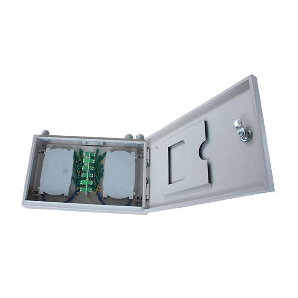
Plan your outdoor fiber installation carefully by surveying the site, choosing the right cable type, and following FOA and OSP standards to ensure reliability. Select the best installation method—direct burial, aerial, conduit, or underwater—based on your environment and. Underground cables are pulled in conduit that is buried underground, usually 1-1. 2 meters (3-4 feet) deep to reduce the likelihood of accidentally being dug up. In extreme cold climates, cables may need to be buried at greater depths where there temperatures are colder and frost penetrates to. We are Jera line, a factory that produces cable infrastructure products. FODB-8 is installed with adapters, splitters, drop cable patchcords, pole bandings, and fiber cable slack storage. Use. pport cables and splice enclosures. Cost of rack Wire Splice B x (200 (50' Mi As ve 1'-0" wide (min) concrete apron. rons shall be sloped away from box. Cost of apron o d oun. FTTP or fiber To The Premises applications have reinforced the importance of reliable and stable fiber optic terminations. Good quality fiber laying and termination systems help achieve minimal back reflection and low signal loss. They also feature resistance to moisture, impact, chemical exposure. Fiber optic cable may be installed indoors or outdoors using several different installation processes. Outdoor cable may be direct buried, pulled or blown into conduit or innerduct, or installed aerially between poles.
[PDF]
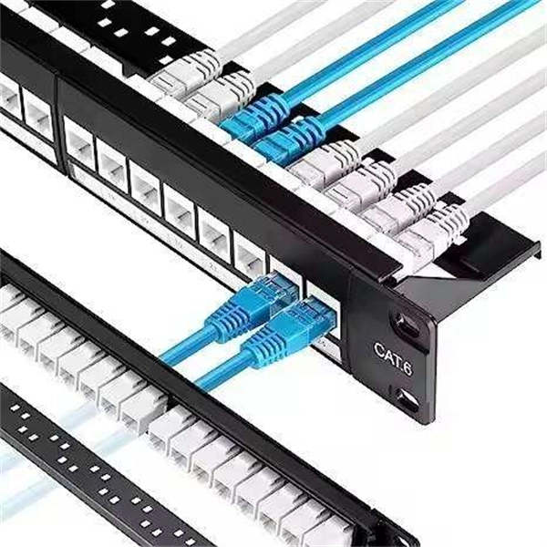
Here's a step-by-step guide to help you properly arrange fiber optic patch panels in a data center environment. Before installation, assess your network's current and future needs:. Effectively arranging optical fiber optic patch cords in a cabinet is a critical aspect of maintaining a streamlined and organized network infrastructure. Proper arrangement not only enhances the overall aesthetics of the cabinet but also plays a crucial role in preventing signal interference and. As networks move to higher speeds and higher density, choosing the right fiber optic patch cords becomes critical to the reliability of your system. At ZION Communication, we design and manufacture a full range of fiber patch cords for: This guide will help you quickly understand the main types of. You need fiber patch cord installation and maintenance for a strong network. If you do not handle them well, connectors can get misaligned. Rough handling can also cause problems. Fiber optic patch cords, also known as fiber optic patch cables or fiber jumpers, are indispensable components in modern optical networks. They act as the critical link for interconnecting devices like optical switches, servers, and distribution frames. Understanding the various technical. You need fiber optic cables. But the options are overwhelming. One customer ordered 50 LC-SC patch cords. They were all the wrong polish type. The network failed during testing. This happens more than you think.
[PDF]

This video shows real on-site footage of electrical installation, demonstrating safe and standardized wiring methods used by professionals. The National Electrical Code (NEC) Section 700. 10 provides critical guidelines for the wiring of emergency systems. These systems ensure continued operation during power outages, protecting lives and maintaining functionality in key buildings. This guide breaks down the essential requirements of. Emergency system circuits supply power to critical life safety loads such as emergency lighting, fire alarm systems, fire pumps, smoke control systems, and essential communication and control circuits. Correct wiring design for emergency system circuits is essential to maintain power integrity. The general rule in 700. 10 (B) is to keep wiring from an emergency source or emergency source distribution overcurrent device to the emergency loads entirely separate from all other wiring and equipment, unless otherwise permitted in 700. 10 (B) (1) through (5). 12) of the interruption of the normal electrical supply.
[PDF]

It plugs into network equipment (like switches, routers, or servers) and its primary function is to convert electrical signals from the device into light signals for transmission over fiber optic cables, and then convert received light signals back into electrical signals. People can also refer to an optical transceiver as a fibre optic transceiver or optical module. A transceiver is a mix of the words 'transmitter' and 'receiver. ' An optical transceiver includes an optical. This section explains the core IP and optical components used in traditional hierarchical networks. It helps readers understand the router, transponder, ROADM, amplifier, and management elements that form the baseline network architecture. In fiber optics, this data is sent in the form of pulses of light over an optical fiber, at very high speeds and across long distances. Essentially, these devices. Why choose Nokia for your optical network? The Nokia industry-leading optical network portfolio leverages highly vertically integrated coherent optical engines and includes the latest generation of open and flexible optical line systems, intelligent coherent pluggables, ultra power-efficient. This page provides an introduction to optical wireless networks. It compares short-range (directed and diffused) and long-range optical wireless technologies, highlighting their differences. The broadband wireless.
[PDF]

The fiber cores of GYTC8S53 fiber cable is from 2 cores to 288 cores GYTC8S53 is a self-supporting fiber optical cable for outdoor use. Commonly referred to as figure 8 cable, figure 8 fiber cable, figure 8 aerial cable, self-supporting figure 8 cable, or simply figure 8 optical cable, this ingenious structure combines optical fibers with an integrated messenger wire in a distinctive “8” cross-section. This self-supporting design. Hunan GL Technology Co., Ltd Supply 2-144 Cores GYFTC8S Aerial Stranded Figure 8 Fiber Optic Cable With Factory Price, Support OEM, All the figure 8 cables supplied from GL FIBER are complied with IEC 60794-4、 IEC 60793、TIA/EIA 598 A standards. In the GYFTC8S cable, single-mode/multimode fibers are. GYTC8Y is a typical self supporting outdoor fiber optic cable with features of moisture resistance and crush resistance suitable for aerial application. The stranded wires as the supporting part are completed with a polyethylene (PE) sheath to be figure 8 structure. After being coated with steel tape longitudinally, a layer of PE inner sheath is extruded, and then a single layer or double layer thin round steel tape armor is longitudinally wrapped After installation, the. l fibers in loose tubes filled with interstitial gel. Aluminum moisture barr er tape or steel tape armoring options are availa le. A steel messenger wire provides tensile strength. It can work at the temperature from -10 to +70℃.
[PDF]

This video shows real on-site footage of electrical installation, demonstrating safe and standardized wiring methods used by professionals. more Learn how to wire a distribution box step by step! This video shows real on-site footage of. Material preparation: Prepare the required circuit breakers, wires, wiring ties and other materials, and ensure that they meet the design drawings and installation requirements. Location determination: Determine the installation position of the circuit breaker according to the position of the. Learn how to install a distribution box safely and correctly. Covers wiring, placement, standards, and expert tips for a compliant setup. A distribution box is the heart of any electrical system. It takes the incoming power and safely distributes it to different circuits throughout your building. It serves as a central hub for distributing electricity throughout a building, ensuring that power is delivered safely and efficiently to all the required locations. This video highlights the installation process for CANTEX Exposed Weatherproof PVC electrical boxes. When an electrical connection is needed outside of a home, commercial or industrial building---or anywhere it might be exposed to the elements, weatherproof electrical boxes and covers are required. It has three categories: residential, commercial and industrial electrical distribution boxes, all of which play important roles in their respective electrical.
[PDF]
The timeframe for splicing a fiber optic cable can vary depending on the type of splice, the equipment used, and the level of expertise of the technician. In this article, we will delve into the details of the splicing process and explore the. Fiber optic splicing involves joining two fiber optic cables to create a continuous optical path. This is typically done when the cable length is insufficient or when the fiber network is damaged and needs restoration. Fusion splicing provides a low-loss, highly reliable connection by melting and fusing fiber ends, making it ideal for long-haul. Fusion splicing is the process of fusing or welding two fibers together usually by an electric arc. Fusion splicing is the most widely used method of splicing as it provides for the lowest loss and least reflectance, as well as providing the strongest and most reliable joint between two fibers. There are numerous use cases for fiber optic splicing. As. This is where fiber optic cable splicing—the process of creating a permanent, high-performance join between two fiber ends—becomes critical. For network managers and technicians, a poor splice can lead to significant signal degradation, network downtime, and costly troubleshooting.
[PDF]

A lighting control module operates as the central controller for a lighting system. It receives input from switches, apps, or sensors and regulates electrical flow to connected lights. Depending on the setup, it adjusts brightness, color temperature, or full lighting scenes. It acts as a bridge between your physical lighting fixtures and the smart systems that manage them. Instead of relying solely on traditional wall switches, you can control your lights via remotes, mobile or web apps. A lighting control module is an essential component in a lighting control system that manages how lights are powered, dimmed, or switched on and off. Think of it as the “brain” that receives commands—either from a manual switch, a sensor, or a building automation system—and translates them into. A lighting control module is a smart device that manages lighting circuits, adjusting brightness, automating schedules, and responding to sensors. It enhances comfort, efficiency, and ambience in homes and commercial spaces. Explore the multifaceted benefits and applications of lighting control modules, from home automation to industrial. These modules are designed to communicate with various sensors, switches, and control panels, making lighting adaptable to different environments and user preferences. It enables precise management of lighting systems, allowing for adjustments in brightness, color, timing, and even integration with other smart devices. This innovation.
[PDF]