
When it comes to testing fiber optic cables, a Visual Fault Locator (VFL) is an essential tool in your toolkit. A VFL is used to detect faults, breaks, or bends in fiber optic cables by emitting a bright red light that is visible even through the fiber's jacket. Let's dive into everything you need to know about mastering VFLs. In the. Finding a break in a fiber optic cable can be challenging but is essential for maintaining a stable network. Common Indicators of a Cable Break Signal. Here Kingfisher's experienced engineers share their experience in best practices and procedures for fiber optic testing related mostly to installation and maintenance. We hope that by sharing our knowledge, we will help grow our industry. Please enjoy & pass on these notes. The following are key methods and techniques used for optical fiber cable line failure positioning: Visual Inspection: Perform a visual inspection of the. Locating faults in fiber optic cables requires specialized tools and techniques. Look for dirt, scratches, or damage on the connectors. Clean. To ensure the quality and continuity of fiber optic services, it is essential to identify and locate fiber optic cable faults as quickly and accurately as possible. In this article, you will learn about some of the common methods and tools for fiber optic testing and troubleshooting.
[PDF]

The vertical line that split the box in two is the median. Sometimes, the mean is also indicated by a dot or a cross on the box plot. The whiskers are the two lines outside the box, that go from the minimum to the lower quartile (the start of the box) and then from the upper quartile (the end of. Box plots (also called box-and-whisker plots or box-whisker plots) give a good graphical image of the concentration of the data. They also show how far the extreme values are from most of the data. A box plot is constructed from five values: the minimum value, the first quartile, the median, the. The histogram, dot plot and box plot in each separate section represent the same data set. Symmetric (bell shaped) - when graphed, a vertical line drawn at the center will form mirror images, with the left half of the graph being the mirror image of the right half of the graph. Individual scores are represented by dots. Since the scores have been rounded to the nearest second, any given dot might represent more than one score. A box plot displays a ton of information in a simplified format. Analysts frequently use them. Use box plots, also known as box-and-whisker plots, to show the distribution of values along an axis. Boxes indicate the middle 50 percent of the data (that is, the middle two quartiles of the data's distribution). You can configure lines, called whiskers, to display all points within 1.
[PDF]

An optical network is a communication system that leverages light to convey information across distances, encoding data into rapid flashes of light instead of relying on electrical voltage changes. At the heart of this ecosystem lies the Optical Transport Network (OTN) — a framework defined by the ITU-T (notably G. 709) that has become the foundation for modern optical communications. This method allows engineers to manage the exponential growth in global data traffic generated by. A passive optical network (PON) is a system commonly used by telecommunications network providers that brings fiber optic cabling and signals all or most of the way to the end user. Depending on where the PON terminates, the system can be described as fiber to the curb, fiber to the building or. An Optical Transport Network (OTN) is a transmission network based on wavelength division multiplexing (WDM) technology. It is a specific type of transmission network that transmits data and manages it using optical signals. OTN is built on a series of protocols, including G. It is designed to provide a high-speed, scalable, and reliable infrastructure for the transmission of data between different network nodes. While there are many subtle differences, a clear distinction between active optical networking and PON topology is PON's use of a.
[PDF]

This video shows real on-site footage of electrical installation, demonstrating safe and standardized wiring methods used by professionals. The National Electrical Code (NEC) Section 700. 10 provides critical guidelines for the wiring of emergency systems. These systems ensure continued operation during power outages, protecting lives and maintaining functionality in key buildings. This guide breaks down the essential requirements of. Emergency system circuits supply power to critical life safety loads such as emergency lighting, fire alarm systems, fire pumps, smoke control systems, and essential communication and control circuits. Correct wiring design for emergency system circuits is essential to maintain power integrity. The general rule in 700. 10 (B) is to keep wiring from an emergency source or emergency source distribution overcurrent device to the emergency loads entirely separate from all other wiring and equipment, unless otherwise permitted in 700. 10 (B) (1) through (5). 12) of the interruption of the normal electrical supply.
[PDF]
Long-haul transmission uses fiber optic cables to send data quickly and securely over long distances, connecting cities and countries for fast communication. Whether you're connecting a data center or simply linking your home office to a shop, it's important to understand the fundamental aspects of fiber optic. Long-distance fiber optic transmission is a fascinating field where physics, engineering, and innovation converge to power our digital lives. By leveraging technologies like DWDM, optical amplification, and high-performance coherent optical transceivers from industry leaders like LINK-PP, we. Fiber optic cable transmission distance is determined by two primary physical factors that affect signal quality as light travels through the fiber medium. Attenuation is the progressive loss of signal strength that occurs as light travels through the fiber. The greater the distance, the greater. Fiber optic cables have revolutionized modern communication networks by enabling blazing-fast data transmission across vast distances. However, fiber cable runs are not limitless. This exploration examines their workings, efficiency principles, and modern applications. Glossary terms are explained in the Glossary Section. A fiber optic cable can contain a varying number of glass fibers, from a few up to a couple hundred. Another glass layer called cladding surrounds the glass fiber.
[PDF]
A dedicated fiber line typically provides businesses with dedicated Internet access, delivering a private, high-speed connection through fiber-optic cables. Unlike shared networks that divide bandwidth and cause slowdowns, it guarantees consistent performance with symmetrical upload and download. What Is Dedicated Fiber Internet? Dedicated fiber internet is a type of internet service that uses fiber optic cables to provide a dedicated and exclusive connection to a user. This means the connection is not shared with other users, resulting in faster and more reliable speeds. Dedicated fiber. Dedicated Fiber, also known as dedicated internet access (DIA), is a premium internet service that provides businesses with a direct fiber optical connection to the internet. It caters to the needs of those who demand the best online performance. Unlike shared broadband services, where multiple users draw from the same network capacity, dedicated fiber provides guaranteed bandwidth that is. When you have a dedicated internet line, it implies a confidential link between your office and the Internet Service Provider. With a dedicated line, you always get exactly what you pay for. Unlike traditional broadband that shares capacity amongst multiple users, leased lines offer what's.
[PDF]

Definition: Optical Line Terminal or optical line termination is a device that basically acts as a part of a passive optical network (PON). It is present in the central office of the network and manages the transmission and reception of information across the overall network. Optical line terminal. A GEPON system usually consists of an OLT (Optical Line Terminal) at the service provider's central office and multiple ONU (Optical Network Units) or ONT (Optical Network Terminals) close to the end user as optical splitters. In addition, the transmission between OLT and ONU/ONT adopts an optical. An Optical Line Terminal (OLT) is a fundamental element within optical communication networks, serving as a hub that facilitates the transmission and reception of data, voice, and video services to and from subscribers' locations. It acts as the central point for controlling and managing network. In optical fiber technology, one of the most widely used devices is an optical line terminal, also called OLT. It can transmit and receive data at several hundreds of kilometers without loss. The OLT is responsible for converting incoming optical signals into electrical signals, which are.
[PDF]

- **Third-level Distribution Box**: That is, the switch box, which is at the end of the power distribution system and directly provides power for electrical equipment. It is closely connected to the electrical equipment. A distribution box is installed under the main distribution box, and a switch box is installed under the distribution box. "Two level protection" mainly refers to the use of leakage protection measures. In. Note: Distributions by generation are defined by birth year as follows: Silent and Earlier=born before 1946, Baby Boomer=born 1946-1964, Gen X=born 1965-1980, and Millennial=born 1981 or later. Last Update: March 27, 2026 The Federal Reserve Board of Governors in Washington DC. Residential utility pole diagrams are essential for understanding the infrastructure that provides electricity, telephone, and internet services to homes. The following is a detailed introduction about it: - **First-level Distribution. Electric power distribution is the final stage in the delivery of electricity. Electricity is carried from the transmission system to individual consumers. Distribution substations connect to the transmission system and lower the transmission voltage to medium voltage ranging between 2 kV and 33 kV.
[PDF]

CT-S3T-2 tower section weight does not exceed 26 kg. Transmission tower weight per meter varies dramatically by voltage level: 35kV towers average 100-180 kg/m, 66kV systems run 150-250 kg/m, 110kV towers range 200-450 kg/m, 220kV structures reach 350-600 kg/m, and 500kV ultra-high voltage towers require 500-800 kg/m. This weight increases. Due to the complicated nature of tower infrastructure, it can prove invaluable to have an engineer approved recommendation for solutions that will accommodate your particular project. We offer a Tower Recommendation Proposal Consultation Service, providing a detailed report that you can use for the. 18m Telecom Tower Ma /www. inf. ASMTower automatically performs load calculation on telecom structures, wind load, ice load and dead load according to the following design standards: ASMTower performs wind and ice load calculations according to the chosen code and distributes the resulting loads, along with the weight of the. Get Latest Price from the seller Khan Enterprises - Offering Selp Sport Wi-Fi Tower, Size: 18 Mtr Rtt at ₹ 3500/meter in Bengaluru, Karnataka. Get WiFi Tower at lowest price | ID: 20500615430. Now, let's take a look at the pricing options: 1. Non-upgradeable: • 12 meters: R49,990. 00 ex VAT ex works PLUS R49,000. 00 ex VAT for site visit, civils, and installation.
[PDF]

In this weekly how-to, powered by KnowHow, we'll walk you through how to safely set up, test, and troubleshoot a spider box in the field. Supplying temporary power on construction sites is essential for running equipment, lighting systems, and temporary facilities. However, the dynamic and harsh nature of construction environments makes electrical safety and reliability a major challenge. Modern solutions rely on portable. Whether you need an industrial portable power station, a complete jobsite power station, or help managing temporary wiring and distribution, this will help you stay compliant with all the necessary requirements. Temporary power systems tend to be exposed to harsh environments and frequent use. This includes MCCB, MCB, DB boxes, cable management, earthing and load distribution for machines. more In this video we are showing a complete Construction Site Electrical Distribution Panel setup. This. Temporary power distribution boxes provide a safer way to manage power while keeping your workspace tidy. Construction site power varies from one project to another, with some projects requiring far more energy than others. However, adding.
[PDF]

In this guide, we'll walk you through the entire process of preparing fiber optic cable for splicing and termination to fiber connectors. We'll explore the necessary tools, safety precautions, and step-by-step procedures for cable connectors, mechanical and fusion. At the heart of any robust fiber optic network lies a crucial process: Preparing a fiber cable for termination of a connector or splice. Two types of splices are used in fiber optic cabling one is Mechanical the other is Fusion. Whether you're installing a new network, expanding an existing one, or. Splicing fiber optic cable is an extremely important phase for making dependable, high-speed communication infrastructures. Regardless of the type of fiber network you're deploying, be it for telecom, enterprise data centers, or smart city infrastructure, fusion splicing provides the benefits of. Think of a fiber optic cable splice as the seamless stitching that keeps data flowing through the delicate threads of a network—like a master tailor joining fabric with precision. This article explains when. We terminate fiber optic cable two ways - with connectors that can mate two fibers to create a temporary joint and/or connect the fiber to a piece of network gear or with splices which create a permanent joint between the two fibers. These terminations must be of the right style, installed in a. So in essence, fiber optic splicing is a process used to join two separate fiber optic cables together.
[PDF]

At the core of a beam splitter's functionality is its ability to split an incoming light beam into multiple paths. This is typically achieved through processes of refraction, reflection, or diffraction. It is a crucial part of many optical experimental and measurement systems, such as interferometers, also finding widespread application in fibre optic telecommunications. In its. 📦 For purchasing, use the RP Photonics Buyer's Guide for beam splitters. It provides an expert-curated supplier directory, buyer-focused technical background information, and structured selection criteria to support professional procurement decisions. This passive device uses a specialized surface designed to both reflect and transmit light simultaneously. The resulting beams are directed along different paths, allowing a single light. Beam splitters are essential optical components used to divide a beam of light into two or more separate beams. They play a crucial role in various scientific, industrial, and everyday applications. Its fundamental purpose is to precisely control the path and intensity of light, making it a ubiquitous component across various optical systems.
[PDF]

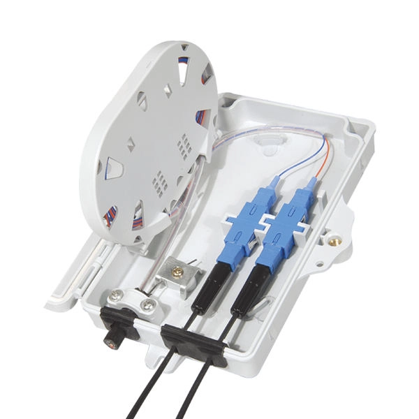
This complete guide covers everything from identifying causes of failure to advanced repair techniques, drawing on the latest industry standards and innovations. A fiber termination box is the standard instrument used in fiber optic networks to connect, secure, and protect optical fibers at the terminating point. Proper installation and maintenance of FTBs are essential to ensure the reliability and performance of the network infrastructure. Before. By understanding these key elements and following the outlined steps, you can effectively repair fiber optic cables and maintain the high-performance network necessary for today's demanding communication needs. Whether you're a network technician, IT professional, or telecom operator, you'll find practical steps, tools, and tips to restore. FTTP or fiber To The Premises applications have reinforced the importance of reliable and stable fiber optic terminations. Good quality fiber laying and termination systems help achieve minimal back reflection and low signal loss. They also feature resistance to moisture, impact, chemical exposure. A fiber optic distribution box, also known as a fiber optic terminal box or fiber optic termination box, is a device used to connect and manage fiber optic cables in a network. The distribution box provides.
[PDF]