
A Fiber optic cap type splice box is a protective enclosure designed to house and organize fiber optic splices. It typically features a dome or cap-style closure that provides a sealed environment for fiber joints, protecting them from external conditions. As fiber optic networks continue to expand across urban, rural, and industrial environments, the reliability of connection points becomes. The cap-type splice box is mainly designed for laying optical cables in overhead and tunnels. It does not meet the waterproof requirements of the regulations when used in direct-buried lines, but the moisture-proof effect in lines is better. According to regulations, the open type and other three. The types of optical cable splice boxes can be divided into cap-type optical cable joint boxes and horizontal optical cable joint boxes according to the shape and structure. According to. Grandway's fiber optic closure provides a high density wall mounted or pole mounted solution for next generation networks, which aims to provide and manage fiber splitters in a limited space. It is designed for FTTH (Fiber to the Home) or FTTB (Fiber to the Building) with protective housing for all. Briefly explain how fiber splice closures are critical for network protection and performance optimization. Introduce that choosing between dome (cap-style) and horizontal (in-line) closures depends on specific project requirements. Understanding Fiber Splice Closure Types 1.
[PDF]

Numerous disciplines, including photonics, telecommunications, biomedical imaging, and quantum computation, make extensive use of cube beam splitters and their techniques for manipulating light. A beam splitter or beamsplitter is an optical device that splits a beam of light into a transmitted and a reflected beam. It is a crucial part of many optical experimental and measurement systems, such as interferometers, also finding widespread application in fibre optic telecommunications. A typical cube beam splitter consists of two prisms with right-angle faces that are joined at their hypotenuses. A special dielectric coating is applied to one of these surfaces, which. 📦 For purchasing, use the RP Photonics Buyer's Guide for beam splitters. It provides an expert-curated supplier directory, buyer-focused technical background information, and structured selection criteria to support professional procurement decisions. What are Beam Splitters? A beam splitter (or. Plate beamsplitters are flat substrates with a partially reflecting coating on one surface that divides the optical beam based on power or wavelength. No epoxy or optical contacting is used in fabrication, making plate beamsplitters intrinsically suitable to high energy applications. They come in different types and have numerous applications. However, most do not know how they work.
[PDF]

Relay protection is the discipline of designing schemes that detect faults, coordinate relays, and isolate equipment without outages. It emphasizes selectivity, coordination, fault response, and system behavior rather than individual relay devices. Relay protection is often misunderstood as a. A protective relay is an intelligent electrical device designed to detect faults in power systems and initiate corrective actions such as tripping a circuit breaker. : 4 The first protective relays were electromagnetic. This document provides recommendations, background and philosophy on relay protection that is not available in M07. The facilities to which this Document applies are generally comprised of the fol-lowing: In analyzing the relaying practices to meet the broad objectives set forth, consideration must. What is a Protective Relay? A protective relay is an intelligent device that senses abnormal electrical conditions, such as overcurrent, under-voltage, or frequency deviations. It initiates the operation of circuit breakers to isolate the affected section. This prevents damage to equipment, reduces. Protective relays and devices have been developed over 100 years ago to provide “lastline”of defense for the electrical systems. They are intended to quickly identify a fault and isolate it so the balance of the system continue to run under normal conditions. The selection and applications of.
[PDF]
A photonic integrated circuit (PIC) or integrated optical circuit is a microchip containing two or more photonic components that form a functioning circuit. This technology detects, generates, transports, and processes light. Photonic integrated circuits use photons (or particles of light) as. architecture and performance of several generations of InP-based PICs. Increased complexity in chip functionality has resulted in a need for increased fabricati n complexity from III-V epitaxy, through wafer fab, die fab, and test. Through continuous learning and improvement, Infinera has. Photonic integrated circuits (PICs) use light (photons) to transmit information, whereas traditional integrated circuits use electricity (electrons), enabling faster signal propagation. Whereas an electronic integrated circuit.
[PDF]

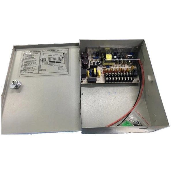
A distribution box, also known as a junction box or distribution point, is a enclosure or housing used to distribute electrical or telecommunications cables to multiple directions. A distribution box (DB box) is a key part of electrical wiring, acting as a central hub where cables branch out to various outlets and switches in a building. It supports different cable sizes and types, enabling smooth and fast power distribution. Each. Distribution boxes, also known as electrical distribution boards or panels, are pivotal components in electrical systems, ensuring the safe and organized distribution of electrical power throughout residential, commercial, and industrial environments. These boxes house various circuit breakers. With the new distribution box, centrally routed cables can be distributed 360° in all desired directions. Cables with and without connectors can be routed, sealed with IP54 (acc. to 60529) and strain relieved in accordance with EN 62444. This article will provide a detailed introduction to electrical distribution boxes, including their functions, components, types, and uses. Today, electrical systems are essential for homes and industries. But what exactly is a power distribution box, and why is it so essential in our daily lives? The DB panel board controls the flow of electricity.
[PDF]

Every fiber optic patch cable has a rated attenuation and bandwidth. For example, OM1 is rated at 200 MHz·km at 850 nm and is intended for use in legacy applications. The higher OM ratings provide more speed and distance. Attenuation should remain within acceptable limits for reliable transmission. Executive Summary: Choosing the right fiber patch cable is one of the most consequential decisions in network infrastructure planning. The wrong choice — whether it's an underperforming multimode grade or an unnecessarily expensive singlemode run — can either cripple your network's reliability or. Fiber optic patch cords are key components for efficient, low-loss optical signal transmission between devices and fiber optic cabling links. One or both ends of the patch cord are equipped with standardized fiber optic connectors, and common interfaces include LC, SC, FC, ST, etc. They are manufactured and tested in compliance with TIA 604 (FOCIS), IEC 61754 and YD/T industry standards. OM1, OM2, OM3, OM4, OM5 or OS2 fiber types are available to meet the demand of. Fiber optic patch cables are ideal for supporting high speed telecommunication network fiber applications. They are lengths of optical fiber terminated with connectors on both ends. Their job is to connect two optical devices, like switches, routers, or optical transceivers that communicate.
[PDF]

An optical receiver is an electronic device that detects and converts optical signals into electrical signals. The primary function of an optical receiver in digital TV setups is to facilitate the transmission of high-quality audio signals between. In this architecture, optical fiber carries signals from the headend to distribution nodes across long distances, after which coaxial cable completes the final delivery to subscribers. He oversaw the day-to-day operations of the site to ensure readers have the most up-to-date information on everything from operating systems to gadgets. Prior to his current. othing beats surround sound for movies and TV — and surround sound starts with a home theater receiver. But a receiver can give you a lot more than that. During my time as a Crutchfield Sales Advisor, I helped many people choose the receiver that worked best for them. They are a step above the previously used analog audio outs. The most common types are optical and coaxial. The rest of this article will delve into how digital audio output works, how its types differ, and. When it comes to enhancing your home entertainment experience, connecting your optical TV cable to your home theater system is an essential step that can significantly elevate your audio-visual enjoyment. This guide will walk you through the process in detail, ensuring that you have all the.
[PDF]

Managing optical attenuation helps keep your signal safe. Clean your optical connectors so you do not lose. Optical Signal Attenuation is the single greatest factor limiting the distance and performance of your network. Understanding it is crucial for anyone involved in data centers, telecommunications, or enterprise networking. This guide will demystify signal loss, explore its causes, and show you how. In high-speed environments, where the optical link budget is measured in fractions of a decibel, diagnosing and eliminating unexpected loss is the network engineer's most critical task. This field guide provides a systematic, step-by-step approach to troubleshooting and resolving the most common. Signal loss in Fiber Optic networks can make data slow. It can also break your connection. You should fix it fast to get speed and stability back. > You can solve this with simple steps. Signal Degradation (Loss of Light) When the signal quality degrades, it could be a sign of attenuation or excessive loss in the system. The signal might become weaker, resulting in slower speeds or dropped connections. -. Fiber optic networks are celebrated for their speed and reliability, but even the best systems can encounter problems. When issues like signal loss, slow speeds, or intermittent connectivity arise, systematic troubleshooting is key. Things like impurities in the fiber core and reflections at the core-cladding edge cause this drop.
[PDF]
Flex electrical cable, often referred to as flexible cable or flex, is a type of wire that is designed to withstand repetitive bending and movement without damage. Article 400 covers the general requirements and applications for flexible cords as contained in Table 400. A “flexible cord” is two or more insulated conductors enclosed in a flexible covering. Figure 01 The NEC does not. What is a flexible cable? Flexible cables are cables that have multiple conductors (Class 5 or Class 6 conductors) that form the conductor and are insulated and sheathed in a lightweight, flexible material (usually plastic or rubber). Why choose flexible cables for domestic use? It is suitable for. These include flat flexible cable (FFC), stranded wire, power cables, control cables, and flexible electrical conduit. Each type meets specific needs across industries like automotive, electronics, and medical devices. Here is a quick look at how leading cable types are used worldwide: You can. Power distribution cables present a unique challenge to electrical wire interconnect system engineers. Unlike rigid electrical wiring, which is designed for static installations within buildings, walls, or. In any electrical system—whether powering lights in homes, machinery in factories, or robots in operation—cables are the unsung heroes, safely and reliably transmitting electrical energy. As the backbone of power distribution systems, cables connect power sources (such as circuit breakers) to.
[PDF]

Circuit breaker wiring configurations involve organizing main switches, busbars, and branch breakers within a distribution box. Proper setups ensure balanced electrical loads, ground fault protection, and easy maintenance. Messy distribution boxes are dangerous and very hard to fix. This guide shows you how to organize circuit breaker wiring properly. You will learn to build a safe, efficient, and professional electrical system today. Location determination: Determine the installation position of the circuit breaker according to the position of the. The distribution board is the heart of every electrical installation. This guide covers split load vs dual RCD vs RCBO board configurations, circuit arrangement and allocation, BS 7671 labelling requirements, type testing under BS EN 61439, SPD installation, wiring best practice, and the common. Distribution panels, breaker panels, load center, and/or distribution boards—any name you call them, they're a key part of every electrical system. Wiring distribution panels serve as the central hub and nerve center, routing power from the main service feed to multiple circuits. When setting up. Hey, in this article we are going to see the Single Phase Distribution Box Wiring Diagram and Connection Procedure. It serves as a central hub for distributing electricity throughout a building, ensuring that power is delivered safely and efficiently to all the required locations.
[PDF]
Photovoltaic modules, or solar modules, are devices that gather energy from the sun and convert it into electrical power through the use of semiconductor-based cells. A photovoltaic module contains numerous photovoltaic cells that operate in tandem to produce electricity. A single PV device is known as a cell. An individual PV cell is usually small, typically producing about 1 or 2 watts of power. These cells are made of different. Photovoltaics (PV) is the conversion of light into electricity using semiconducting materials that exhibit the photovoltaic effect, a phenomenon studied in physics, photochemistry, and electrochemistry. Here is a description of their main features and of Enel Green Power's innovative solution. A semiconductor.
[PDF]

The main electrical appliances are refrigerator, induction cooker and microwave oven The air conditioner switch needs to be replaced, as does the main switch. The main switch does not have leakage. Because the human body passes 30mA with. A distribution box is installed under the main distribution box, and a switch box is installed under the distribution box. Electrical equipment is installed under the switch box, forming a three-level distribution. "Two level protection" mainly refers to the use of leakage protection measures. In. In a newly constructed residential area, a 10kV power line is introduced into the substation. After stepping down the voltage through the transformer's low-voltage side (0. From there, it is routed to individual building distribution boxes (secondary distribution boxes), which subsequently supply power to unit-level distribution boxes. The power distribution boxes deliver electricity from the main electrical main to other circuits. Several distribution boxes are designed for specific use in offices or industries. Main Distribution Board (MDB) 2. The distribution box serves as the load centre and distributor of electrical power. It is the central electrical supply system of any.
[PDF]

Members of the Cabinet are political appointees and administratively operate their departments. For the current cabinet, see Second cabinet of Donald Trump. The Cabinet of the United States is the principal official advisory body to the president of the United States. The Cabinet generally meets with the president in the Cabinet Room adjacent to the Oval Office in the West Wing of the White. Every President has a lot to do -- especially a modern-day United States President. He or she must: oversee dealing with foreign countries and the defense of our land. keep an eye on how our farms are doing. make sure that. The purpose of the Cabinet is to advise the President on matters relating to the duties of their respective offices. The Constitution does not directly mention a "Cabinet," but. cabinet, in political systems, a body of advisers to a head of state who also serve as the heads of government departments. The cabinet has become an important element of government wherever legislative powers have been vested in a parliament, but its form differs markedly in various countries, the. The Presidential Cabinet acts as a set of advisors for the president. What Is the US Cabinet? The US Cabinet is a series of departments within the.
[PDF]

