
By providing a physical air gap via photoelectric isolation, this 817 optocoupler board ensures that noise or electrical faults on the load side never reach your expensive processing unit. This voltage level shifter is designed for high-reliability interface driving. Onboard 4-Channel 817 Are Independent:can achieve different voltage control at then same time The output ports are independent of each other. Module Diagram: One Channel of the 4-Channel Optocoupler High-Power Motor Drive Module. Optocoupler Isolation Relay Mo. AC 110V Motor Forward Reverse. The FOD3182 is a 3A output current, high-speed MOSFET gate drive optocoupler. It consists of an aluminium gallium arsenide (AlGaAs) light emitting diode (LED) optically coupled to a CMOS detector with PMOS and NMOS output power transistors integrated circuit power stage. It is ideally suited for. An optocoupler, also known as photo-coupler or opto-isolator, is a component which can transfer an electrical signal across two galvanically¬-isolated circuits by means of optical coupling. Inside the package, an infrared LED on the input side shines onto a phototransistor on the output side. They are sometimes known as opto-isolators, photocouplers, or optical isolators.
[PDF]

The basic design of an optocoupler consists of a light source, usually an LED (Light-Emitting Diode), driven by the input signal which could be a digital or analogue voltage/current depending upon the characteristics of the light source. An optocoupler (or opto-isolator) is a component that transfer signals between circuits using light. In this guide, you'll learn how they work and how you can use one in your own projects. Optocouplers are very useful when you need to isolate different sections of a circuit, for example in power. Optocouplers, also known as opto-isolators, uses infrared light to transfer electrical signals between two electrically isolated circuits and are commonly classified by their photosensitive output device What is an Optocoupler? An optocoupler (also called an opto-isolator, photo-coupler, or optical. An optocoupler is a tiny part that moves signals between circuits without letting electricity jump across. It uses light to do the job, which helps keep things safe. That way, noisy signals, voltage spikes, or weird grounding issues don't mess with sensitive electronics. Opto-isolators prevent high voltages from affecting the system receiving the signal. We will explore the basics of optocoupler selection and their functionality, helping.
[PDF]

A perforated cable tray—also called a ventilated trough tray —features a solid bottom with regularly spaced ventilation holes and continuous side rails. Unlike ladder trays, the bottom surface provides continuous cable support, while the perforations allow limited airflow. Each cable tray type performs a different function and comes in various materials such as aluminum, galvanized steel, and FRP. What is Cable Tray? 1. Non-Metallic What is Cable. An electrical cable tray is a type of containment system used to support insulated electrical cables for power distribution, control, and communication. But what exactly is it, and why is it so important? This ultimate guide will break down everything you need to know about vertical cable trays, ensuring you. A cable tray system is a unit assembly of sections and fittings that forms a rigid structural system used to securely fasten or support cables and wiring. Think of it as a sophisticated “highway” for cables, keeping them organized, protected, and easily accessible.
[PDF]

They provide cost-effective solutions through automated dispensing and streamlined production. With the durability, robust IP67-rated protection, and resistance to vibration and environmental factors, these boxes deliver reliable performance in harsh conditions. A distribution boxes is an essential device that manages the safe and efficient flow of electrical power throughout different areas of a building or facility. It is commonly used in homes, offices, and industrial settings to control and protect electrical circuits. Understanding its significance. Many people think distribution boards and distribution boxes are the same, but they're not. They may sound similar, but they have different roles in electrical systems. Knowing the difference helps you choose the right one for your needs. But how do you choose the right one for your application? In this article, we break down the key types, core functions, and selection tips to help you make an. A distribution box, also known as a power distribution box or electrical distribution box, is used to distribute electrical power safely to multiple circuits. It helps organize, protect, and control electrical connections in residential, commercial, and industrial electrical systems. What is the distribution box? A. One critical component of a septic system is the distribution box (also called a d box). The D box is a.
[PDF]

Key components typically housed within these boxes include circuit breakers, relays, fuses, and switches, all critical for safe electrical distribution in hazardous environments. Flameproof enclosure (Ex d IIB+H2), which can be used as feed distribution equipment in control and distribution system (such as distribution box, switch box of main circuit, control box, terminal box or motor starting box etc. ) ·Enclosure: stainless steel. Equipped with specialized hinge. Explosion proof equipment is designed to contain internal explosions and prevent ignition of surrounding flammable gases or dust. Rather than stopping an explosion from occurring, the equipment safely manages it within a reinforced structure. They house critical components like circuit breakers, relays, and surge protectors in durable materials such as aluminum or stainless steel. They ensure electrical safety by preventing sparks or heat from igniting flammable substances. As industries evolve, understanding how these devices operate becomes essential for engineers, safety managers, and. Explosion-proof Power Distribution Panel MAMX-02 and MAMX-03 * In-built circuit breaker, AC Contactor, Thermorelay, PLC, Transducer, Soft starter and other components, The panel can install indicator, Pushbutton, Universal switch, Display instrument. * Rated current: 1500A * Steel pipe or Cable.
[PDF]

Silicon, toughened glass, aluminum, and electrical metals are carefully chosen materials that are used to make panels that work well and last a long time. All of these parts work together to turn the sun's rays into electricity that can be used. They can be put on roofs or in. We look at the raw materials of a PV module including busbars, and junction boxes to the cell itself. A solar, or photovoltaic (PV) module as it is also called, is a device that converts sunlight into electricity. It is the key component of a solar energy system. Solar panels convert sunlight into. Most panels on the market are made of monocrystalline, polycrystalline, or thin film ("amorphous”) silicon. In this article, we'll explain how solar cells are made and what parts are required to manufacture a solar panel. Most homeowners save around $60,000 over 25 years Solar panels are usually. A solar panel is made of different raw materials like frames, glass, backsheets, and others. Each of the raw materials for solar panels plays an important role in generating electricity. Aluminum Alloy Frames Regarding solar. Discover the key materials that make up modern monocrystalline solar panels, what role each material plays, and where these materials usually come from. Sunlight first passes through a protective layer (usually glass) and then enters the solar cell through a. The cell to module process starts with very pure materials. They also affect how long the panels last.
[PDF]

Circuit breaker wiring configurations involve organizing main switches, busbars, and branch breakers within a distribution box. Proper setups ensure balanced electrical loads, ground fault protection, and easy maintenance. Messy distribution boxes are dangerous and very hard to fix. This guide shows you how to organize circuit breaker wiring properly. You will learn to build a safe, efficient, and professional electrical system today. Location determination: Determine the installation position of the circuit breaker according to the position of the. The distribution board is the heart of every electrical installation. This guide covers split load vs dual RCD vs RCBO board configurations, circuit arrangement and allocation, BS 7671 labelling requirements, type testing under BS EN 61439, SPD installation, wiring best practice, and the common. Distribution panels, breaker panels, load center, and/or distribution boards—any name you call them, they're a key part of every electrical system. Wiring distribution panels serve as the central hub and nerve center, routing power from the main service feed to multiple circuits. When setting up. Hey, in this article we are going to see the Single Phase Distribution Box Wiring Diagram and Connection Procedure. It serves as a central hub for distributing electricity throughout a building, ensuring that power is delivered safely and efficiently to all the required locations.
[PDF]

Fiber optic network diagrams represent the architecture and connectivity of fiber optic systems, and their design philosophy integrates technical, functional, and conceptual aspects. The diagrams abstract complex details of fiber optic systems to make them understandable for. Fiber optic network design refers to the specialized processes leading to a successful installation and operation of a fiber optic network. It includes first determining the type of communication system (s) which will be carried over the network, the geographic layout (premises, campus, outside. A fiber optics network diagram illustrates how high-speed data travels from an internet service provider to end users. These diagrams help engineers plan infrastructure for residential and commercial buildings. It includes detailed mapping of backbone, distribution, and drop connections for FTTH, FTTP, FTTx, and enterprise networks. Planning and design is a process that includes many decisions, involving first defining the communication protocols to be used on the network and defining geographical layout. It also involves selecting transmission equipment.
[PDF]

China is scaling domestic capabilities, with TeraHop*, Hisense, Accezlink, amongst others, shipping millions of modules to power AI interconnects. The global silicon photonics market is projected to reach $9. 2 billion by 2028, with a CAGR of 19. 4% from 2023 to 2028. Asia Pacific is expected to grow at a CAGR of 22. 1% from 2023 to 2028, driven by data center. The increasing adoption of cloud computing, artificial intelligence, and machine learning necessitates more efficient and scalable optical interconnects, where silicon photonics offers a compelling solution due to its cost-effectiveness, miniaturization, and CMOS compatibility. 4% CAGR during the forecast period (2025-2031). Silicon photonics is experiencing strong growth due to the increasing demand for high-speed data transmission in AI, cloud computing. Yole Group unveils its latest photonic market and technology analyses, Silicon Photonics 2025 and Co-Packaged Optics for Data Centers 2025, which explore how AI-driven demand is reshaping connectivity, from transceivers to packaging innovation. 200G/channel will become the new mainstream, enabling. GlobalFoundries (GF) reported fourth-quarter 2025 revenue of $1. 83 billion and highlighted silicon photonics, advanced packaging, and GaN power as central growth engines tied to AI data center buildouts. Communications infrastructure and data center revenue rose 32% year-over-year in Q4 and 29% for.
[PDF]
Photovoltaic modules, or solar modules, are devices that gather energy from the sun and convert it into electrical power through the use of semiconductor-based cells. A photovoltaic module contains numerous photovoltaic cells that operate in tandem to produce electricity. A single PV device is known as a cell. An individual PV cell is usually small, typically producing about 1 or 2 watts of power. These cells are made of different. Photovoltaics (PV) is the conversion of light into electricity using semiconducting materials that exhibit the photovoltaic effect, a phenomenon studied in physics, photochemistry, and electrochemistry. Here is a description of their main features and of Enel Green Power's innovative solution. A semiconductor.
[PDF]
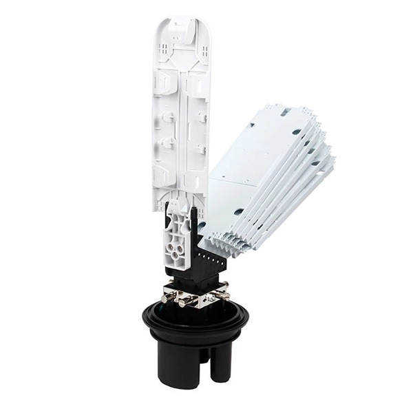
A fiber distribution box (FDB) is a passive enclosure that provides secure splicing, termination, and distribution of optical fibers. It typically contains splice trays, adapters, and cable routing components to manage fiber connections. FDBs are used to. What is a Fiber Optic Distribution Box? A fiber optic distribution box, also known as a fiber optic terminal box or fiber optic termination box, is a device used to connect and manage fiber optic cables in a network. It serves as a central point for fiber optic cable termination, splicing, and. What is a Fiber Optic Termination Box? The Connection Hub at the End of the Fiber Cable A Fiber Optic Termination Box is a small enclosure located at the terminal end of the fiber where it enters your customer premises. Its function is primarily to splice, secure, and protect the optical fibers. In modern FTTH (Fiber to the Home) and optical communication networks, three types of fiber distribution products are widely used: Splitter Distribution Box, ODF (Optical Distribution Frame), and Fiber Terminal Box. They function as junction points that manage, protect, terminate, and distribute fiber optic cables, ensuring efficient data transmission between different.
[PDF]
During an ERG eye test, specialized equipment measures your retina's response to light stimulation. The test uses electrodes, typically in the form of contact lenses or small threads, to record the electrical activity generated by your retina's cells when exposed to different light. The electroretinogram (ERG) is a diagnostic test that measures the electrical activity of the retina in response to a light stimulus. The ERG arises from currents generated directly by retinal neurons in combination with contributions from retinal glia. Importantly, the ERG is an objective measure. Electroretinography, commonly referred to as an ERG test, is a specialized diagnostic procedure used to evaluate the function of the retina—the light-sensitive tissue at the back of the eye. By measuring the retina's electrical responses to light stimuli, this retinal function test plays a crucial. As an essential component of optical fiber communication, optical modules are optoelectronic devices that facilitate the conversion between optical and electrical signals during the transmission process. These cells are known as rods and cones. They form part of the back of the eye known as the retina. The electroretinogram (ERG) is to the retina what the electrocardiogram (ECG) is to the heart. Just as an ECG is crucial to diagnosing illness and monitoring the heart's function, ERG plays.
[PDF]

A beam splitter or beamsplitter is an optical device that splits a beam of light into a transmitted and a reflected beam. It is a crucial part of many optical experimental and measurement systems, such as interferometers, also finding widespread application in fibre optic. Beamsplitters are optical components used to split incident light at a designated ratio into two separate beams. In its. 📦 For purchasing, use the RP Photonics Buyer's Guide for beam splitters. It provides an expert-curated supplier directory, buyer-focused technical background information, and structured selection criteria to support professional procurement decisions. What are Beam Splitters? A beam splitter (or. Beam splitters come in many different forms, including cube and plate configurations, each with its own unique characteristics and applications. Beamsplitters are good at splitting incoming light in specified ratios, and they are required to precisely control light intensity in experiments and. What Is a Beam Splitter? Types, Uses, and How It Works A beam splitter is an optical device that takes a single beam of light and divides it into two separate beams. One portion passes through the device while the other reflects off it, and the ratio between the two can be controlled by design. This passive device uses a specialized surface designed to both reflect and transmit light simultaneously. The resulting beams are directed.
[PDF]
