
This article will give you an overview of the use cases for fiber-optic networking, some of the terms used in fiber networking, and suggestions for setting up a fiber network. Once you understand the basic concepts, you can check out my Recommended Equipment section toward. Fiber tapping is a network tap method that extracts signal from an optical fiber without breaking the connection. Tapping of optical fiber entails diverting some of the signal being transmitted in the core of the fiber into another fiber or a detector. Fiber to the home (FTTH) systems use beam. Optical fiber is a technology used to transmit data by sending short light pulses along a long fiber, which is typically made of glass or plastic. In optical fiber communication, metal wires are preferred for transmission because the signals travel more safely. Optical fibers are also resistant to. Photo: Light pipe: fiber optics means sending light beams down thin strands of plastic or glass by making them bounce repeatedly off the walls. This is a simulated image. Note that in some countries, including the UK, fiber optics is spelled "fibre optics. " If you're looking for information online. This manual covers everything about fiber optic cables, how they work, where they are used, and what is new in this area of technology. The choice of fiber optic cable depends on the specific needs of the application, as well as the.
[PDF]

As a key parameter for evaluating data transmission accuracy, the bit error rate directly determines the reliability and stability of communication systems. This article delves into the fundamentals and testing methods of the bit error rate. A bit error occurs when a single binary digit is flipped during transmission, meaning a logical '0' is mistakenly interpreted as a '1' by the receiver, or a '1' is read as a '0'. Through the interpretation of actual test reports, it. BER is calculated by comparing the transmitted sequence of bits to the received bits and then counting the number of errors. The ratio of how many bits received in error over the total number of bits received is the BER. This ratio is affected by many factors including: signal to noise, distortion. Bit Error Rate (BER) is a crucial metric in signal processing and communication systems, measuring the frequency of errors in data transmission. It is defined as the ratio of the number of bits received in error to the total number of bits transmitted over a communication channel during a specified. In the fast-paced world of digital communication—where billions of bits travel through wires, fibres and wireless links every second—the concept of bit error rate (BER) is both fundamental and profound. It involves measuring the rate at which errors occur in a transmitted bitstream compared to the expected bitstream at the receiver end. The BER measurement helps in assessing the quality.
[PDF]

The basic design of an optocoupler consists of a light source, usually an LED (Light-Emitting Diode), driven by the input signal which could be a digital or analogue voltage/current depending upon the characteristics of the light source. An optocoupler (or opto-isolator) is a component that transfer signals between circuits using light. In this guide, you'll learn how they work and how you can use one in your own projects. Optocouplers are very useful when you need to isolate different sections of a circuit, for example in power. Optocouplers, also known as opto-isolators, uses infrared light to transfer electrical signals between two electrically isolated circuits and are commonly classified by their photosensitive output device What is an Optocoupler? An optocoupler (also called an opto-isolator, photo-coupler, or optical. An optocoupler is a tiny part that moves signals between circuits without letting electricity jump across. It uses light to do the job, which helps keep things safe. That way, noisy signals, voltage spikes, or weird grounding issues don't mess with sensitive electronics. Opto-isolators prevent high voltages from affecting the system receiving the signal. We will explore the basics of optocoupler selection and their functionality, helping.
[PDF]
Shop our range of high-quality fiber optic attenuators for telecom and datacom applications. Use this optical attenuators buying guide to compare major types, define selection criteria, and find suppliers: 🔬 Encyclopedia article: optical attenuators 📦 Top-level product category: optical components and devices Click on a logo to get to the details of that supplier's offer. Our list of. Find reliable variable optical attenuator prices for various models. FS fixed and variable fiber optic attenuators with leading attenuating fibers guarantee consistent and stable fiber attenuation (0~60dB) in WDM transmission. Optical Attenuators Market report is further segmented By Region (North America, Europe, Asia-Pacific, South America, Middle-East and Africa). In 2024, the market for Optical Attenuators Market was valued at USD 1. It is anticipated to grow to USD 2. 5 Billion by 2033, with a CAGR of 9. The types include VOAs made of 2D MEMS having good repeatability and low cost; VOAs made of 1D MEMS having >70 dB high attenuation; VOAs made of fiber directly coupled to fiber MEMS having ultra-low loss <0. We provide support, services, comprehensive training and the resources you need. It's all part of what we do to maximize the value of your VIAVI investment. Contact us for more information or to receive a price quote. We have the experts.
[PDF]

This is where the advantages of fiber optics, specifically indoor fiber optic cable, become apparent. Offering superior bandwidth, lower latency, and enhanced security, it has become the gold standard for future-proofing indoor network infrastructure. Indoor fiber cable is the backbone of modern communication networks within buildings, providing the high-speed data transmission necessary for everything from business operations to home entertainment. As our reliance on fast, reliable internet connectivity grows, so does the importance of. These indoor cabling fibers (drop cables) are those that connect ducts inside the buildings to individual rooms/floors. They are essential for high-rise buildings, data centers, and urban environments containing dense populations where fast, fire-safe, and flexible fiber installations are. Wall-mounted fiber optic wiring boxes are devices used for organizing and managing fiber optic cables in a building or data center. They can be used for various applications such as data transmission, telecommunication, and multimedia. Each type is designed with specific features to ensure optimal performance under varying conditions. This guide explores common indoor cable varieties and their distinct attributes when wiring rooms or structures for high-speed fiber optic links. While outdoor cables.
[PDF]

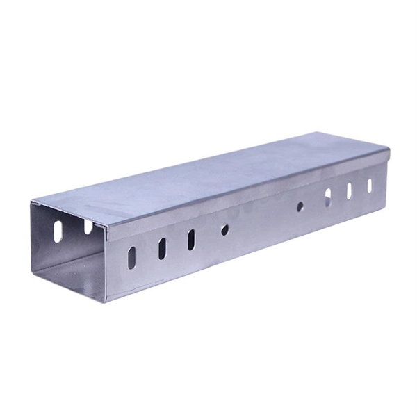
This comprehensive list of top 10 online B2B marketplaces and manufacturers will lead you to find your perfect cable trays based on your business requirements. Let's explore the characteristics of these platforms together. The United States is a diverse landscape of top manufacturers spanning various sectors. These companies lead in innovation, technology, and global competitiveness, employing advanced techniques and contributing significantly to the national economy. They represent excellence in production and. Snake Tray: Snake Tray manufactures innovative cable management and power distribution products all designed to save on installation costs. All of our products have green features and are made in the USA. Established in 1903, nVent ERICO has been an integral rail industry supplier of niche. Other products such as frames, handles, guides, cable rings, shelves, baskets, racks, cable management panels, container holders, shelf dividers & sterilizer carts are available. is estimated to have 10-49 employees. estimated yearly. American Tech Supply a division of American Data provides a complete end cable tray, basket tray and Raceway System solution. Cable Tray and Cable ladder along with wire mesh trays are cable support systems that run large quantities of power or data cable overhead or under floors. com provides buyers with a free hand to explore customized cable.
[PDF]

It plugs into network equipment (like switches, routers, or servers) and its primary function is to convert electrical signals from the device into light signals for transmission over fiber optic cables, and then convert received light signals back into electrical signals. People can also refer to an optical transceiver as a fibre optic transceiver or optical module. A transceiver is a mix of the words 'transmitter' and 'receiver. ' An optical transceiver includes an optical. This section explains the core IP and optical components used in traditional hierarchical networks. It helps readers understand the router, transponder, ROADM, amplifier, and management elements that form the baseline network architecture. In fiber optics, this data is sent in the form of pulses of light over an optical fiber, at very high speeds and across long distances. Essentially, these devices. Why choose Nokia for your optical network? The Nokia industry-leading optical network portfolio leverages highly vertically integrated coherent optical engines and includes the latest generation of open and flexible optical line systems, intelligent coherent pluggables, ultra power-efficient. This page provides an introduction to optical wireless networks. It compares short-range (directed and diffused) and long-range optical wireless technologies, highlighting their differences. The broadband wireless.
[PDF]

This article provides a detailed technical comparison between fiber optic and copper cables, offering a clear perspective for engineers, network architects, and procurement managers. The core distinction between the two technologies lies in the physics of data. However, the exponential growth in data demand has positioned fiber optic technology as the superior alternative for performance, scalability, and future-readiness., 10G/25G/40G/100G and beyond depending on optics and reach). Copper Ethernet scales too, but practical limits are lower and depend. The two main options are fiber optic cables and copper cables, each with its own advantages and drawbacks. Fiber optic cables are praised for their high performance and scalability, while copper cables remain a cost-effective choice, especially for budget-conscious projects and older systems. Copper wire is more susceptible to interference and has limited data capacity, making optical fiber the preferred choice for modern high-speed. Optical connectivity, utilizing fiber-optic technology, has emerged as the superior choice for modern networking, offering unparalleled performance, reliability, and scalability. For example, a typical 10 Gbps copper Ethernet link (such as Cat 6A) over 100 meters can consume approximately 5 to 8+.
[PDF]

When working with laser light, a plate or cube beamsplitter offers the best combination of optical performance and power handling. a beamsplitter is choosing the right coating. Beamsplitters are optical components used to split incident light at a designated ratio into two separate beams. Additionally, beamsplitters can be used in reverse to combine two different beams into a single one. Beamsplitters are often classified according to their construction: cube or plate. A beamsplitter is an optic that splits light into 2 directions. The split ratio of light transmittance and reflectance is 1:1 and is called a half mirror. Good fit for large beam size applications at a reasonable price. This precise ability to direct light paths makes beam splitters essential in various applications, including imaging systems, laser. Plate beamsplitters are made using a coated substrate, and thus exhibit beam offset and ghost reflections from the second surface. Cube beamsplitters avoid beam displacement by working at 0° angle of incidence and placing the coated surface between two right angle prisms, but power handling can be. This Beamsplitters Selection Guide outlines the core types of beamsplitters, explains how they work, and provides practical advice for choosing the best one for your application. Newport offers a wide variety of Beamsplitters in various shapes.
[PDF]

The best router for fiber internet is one that matches your plan speed, home size, and how you use your connection. Our top overall pick is the Netgear Nighthawk RS700S, a Wi-Fi 7 router built for multi-gig fiber plans that handles up to 200 devices across 3,500 square feet. A fiber-optic connection is the best choice for fast home internet as it has a number of advantages compared to traditional copper cables, such as faster speeds and less interference. For budget-conscious. Instead of using your old router, a high-performance Wi-Fi router designed for fiber optic internet will ensure you seamless streaming, online gaming, and remote work all over your space. However, the market is flooded with countless options, making the selection quite overwhelming. Therefore, to help you choose the best routers for fiber internet, the guide below consists of the top options for fiber internet. Ideal for busy households, the router covers up to 2,000 sq. and supports up to 50 connected devices for seamless internet across all rooms and users. Users highlight the simple, intuitive setup process—managing the network and devices easily from the Nighthawk app or browser interface is. After testing dozens of routers specifically for fiber connections, I've found the ones that actually deliver on the promise of high-speed internet. In this guide, I'll share my hands-on experience with the top routers that maximize fiber performance without breaking the bank. Disclosure: As an.
[PDF]
Picking up the best router for fiber internet isn't just about going to the market and choosing one of the best wireless routers. Instead, you need to carefully look at its specs, performance, and the type of securit.
[PDF]
You use a fiber distribution panel to keep fiber optic cables organized. This panel helps you manage cables in your network. The panel protects connections from dust and water. It also shields them from changes in temperature. With the growth of the fiber industry, a wide array of fiber optic patch panels have been developed to fit the many needs of these varying environments. If you already know what your project requires, check out our complete Fiber Patch Panel selection. What is a Fiber Patch Panel? Fiber optic patch. A fiber patch panel is a mounted enclosure—either rack-mounted or wall-mounted—used to terminate, manage, and interconnect multiple fiber optic cables. It acts as a hub for organizing splices and patch cords, streamlining fiber management and preserving signal integrity. You use this device to connect and separate fiber cables. It lets you reach each fiber connection easily.
[PDF]

FTTO is a hybrid network involving fibre optic cabling (pre-terminated or extractable cables) and copper twisted pair patch cords with 8P8C connectors. . It combines passive elements (fibre optic cabling, patch panels, splice boxes, connectors and standard copper 8P8C patch cords) and active mini-switches (called FTTO switches) to provide end devices with Gigabit Ethernet. FTTO involves centralised optical fibre cabling techniques to create a. About the Author : Clifford C. Walker has had a checkered career spanning from 14 years in the British Army, as a Control Technician, before leaving in 1979 and eventually entering the Computer Industry in 1981. His first few companies were associated with Main Frame Computer Installations for both. O) is a standard compliant and decentralised cabling concept for modern ofice environments. It combines the advant ges of highly eficient fiber optic technology with the flexibility of twisted pair cabling. Copper cable only comes to. FTTO highly concentrates the optical communications network for all office, especially for the central business districts (CBD). Get an highly integrated FTTO network solution today! FTTO refer to Fiber To The Office.
[PDF]

