An optical fiber, or optical fibre, is a flexible or plastic that can transmit from one end to the other. Such fibers are widely used in, where they permit transmission over longer distances and at higher (data transfer rates) than electrical cables. Fibers are used instead of metal because signals travel along them with less and are immune to.
[PDF]

Key components of a Passive Optical Network include the Optical Line Terminal (OLT), Optical Network Unit (ONU) or Optical Network Terminal (ONT), Optical Distribution Network (ODN), and Optical Splitters. An OLT is a device used to interface between the service provider's central. The designation “passive” separates these components from active devices, such as lasers, amplifiers, or switches, which rely on electrical power to boost, regenerate, or electronically route a signal. Passive components operate solely by exploiting the fundamental physical properties of light. PON primarily utilizes a point-to-multipoint topology and fiber optical splitters to transmit data from a single point of transmission to multiple user endpoints. The key advantages of PON lie in its ability to offer remote, high-bandwidth, and efficient network connections. Key components of a. Some of the most common optical passive components include optical couplers, optical splitters, optical filters, optical connectors, optical attenuators, optical circulators, optical isolators, optical switches, and optical add/drop multiplexers. A. A device in a passive optical network is something that the transceiver transmits information through, like a modem that sends information through fiber-to-the-home. By eliminating powered components between the service.
[PDF]
The SFP transceiver is not standardized by any official standards body, but rather is specified by a (MSA) among competing manufacturers. The SFP was designed after the interface, and allows greater port density (number of transceivers per given area) than the GBIC, which is why SFP is also known as mini-GBIC. However, as a practical matter, some networking equipment manufacturers engage in pr.
[PDF]

The document discusses optical detectors used in fiber optic communications systems. It describes the functioning of PIN photodetectors and avalanche photodetectors (APDs). Their performance. An optital detector is a device that converts light signals into electrical signals, which can then be amplified and processed. Such detectors are one of the most important components of an optical fiber communcation system and dictate the performance of a fiber optic communication link. PIN Photodiode A PIN photodiode is a widely. Detectors perform the opposite function of light emitters. The most common detector is the semiconductor photodiode, which produces current in response to. It explains how these devices use optical fibers to measure quantities like temperature, mechanical strain, pressure, and vibrations by detecting changes in light propagating through the fiber. A central focus is on sensors based on fiber Bragg gratings, where the Bragg wavelength is sensitive to. Optical Power Meters: These devices measure the power of optical signals in fiber optic cables. This information helps in maintaining signal integrity and quality across the.
[PDF]
Step-by-step cable tray and conduit installation method with safety, quality and inspection procedures as per IEEE standards. But before you lay the first tray or clamp down a single cable, you need a solid plan. This guide breaks down the process step by step. Plan the Route Before You Drill No installation should start without a plan. Mark the cable tray route based on your electrical cable tray design and site. This guide covers the critical steps, from selecting the right electrical cable tray and performing accurate cable fill calculations to managing a safe cable pull through and ensuring all bonding and grounding requirements are met. For licensed electricians, mastering these principles is essential. This method statement describes a detailed procedure for properly installing cable trays and conduits for the Feeder System. The objective is to ensure safety, quality and compliance during the. Below is the detailed cable tray installation method statement not only for cable tray but also applicable for GI ladder and trunking for indoor and outdoor applications and in service rooms like pump rooms, electrical rooms and plant rooms etc. The Cable Tray system is installed in electrical rooms, plant rooms, and service corridors. The key requirements for cable tray installation include: Incorrect installation can lead to overheating, cable damage, or system failure. This is why proper planning and execution are.
[PDF]

The use of locking cabinets with advanced steel and tamper-resistant designs utilizes physical barriers to limit access to sensitive materials, making them harder to reach for unauthorized individuals. This pressure can cause the gap below server cabinets, which is often 2” or more, to become an air stream between hot and cold aisles. The resulting mix of air reduces the effectiveness of a containment solution. The Cool Shield Magnetic Cabinet Skirt provides an easy fix for this issue. These. Commercial environments have evolved as technology advances, and having a robust cabling infrastructure is crucial for scalability, minimising downtime, and enhancing productivity. Educational institutions are increasingly adopting smart technologies and cloud-based resources, so the foundation of. Many network devices are stored in the cabinets. In order to meet the normal operation of these devices in the cabinets, when the computer room cabinets are full of various cabinets and devices, we need to consider how to place the network cabinets? 1. Network cabinet placement skills (1) Before. A network cabinet is defined as a physically enclosed compartment built to store networking gadgets like patch panels, modems, switches, and a multitude of cables. Network cabinets support large, modular network switches by providing additional space for cable management and side-to-side airflow solutions. Networking cabinets tend to have.
[PDF]

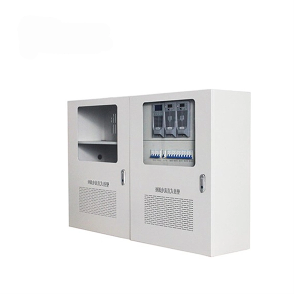
We'll explain what they are, the different panel types you'll encounter, NEC 408 requirements that govern their installation, and common applications for each type. Distribution panels, breaker panels, load center, and/or distribution boards—any name you call them, they're a key part of every electrical system. Wiring distribution panels serve as the central hub and nerve center, routing power from the main service feed to multiple circuits. When setting up. In the world of electrical installations, the term DB box —short for Distribution Board box —refers to the central unit that distributes incoming electrical power to multiple outgoing circuits in a building. Whether you're powering up a residential home, a commercial office, or an industrial plant. Electrical Wiring is a process of connecting cables and wires to the related devices such as fuse, switches, sockets, lights, fans etc. to the main distribution board is a specific structure to the utility pole for continues power supply. It receives power from the main electrical supply and divides it into separate circuits, each. A distribution box, or DB box, is a circuit breaker enclosure. It is a vital part and central hub of any electrical system. It is for the economical use of wiring conductors inside, and outside of a room or building with better load control. Cleat Electrical wiring 2.
[PDF]

So, how do you connect multiple sections together? The answer: use the right connection accessories for a secure, aligned and continuous cable support system. In most cases, sections of wire mesh baskets or electrical cable trays are joined using couplers, bolts, or proprietary. Connecting cable trays correctly is essential for system safety, load stability, and long-term performance. The most common cable tray connection methods include: Each method differs in installation time, cost, flexibility, and strength. The Cable Ladder & Tray Components – Assembly Guide presents a comprehensive visual walkthrough of the assembly and installation process for cable ladder and tray systems. The images meticulously detail each component involved, including ladder sections, cross-members, splices, and tray segments. Make a 90 Gusset Bend in Cable Tray with Two Pieces Easy Way To Connect Pipes 17. Joining Cable Tray - Three Sytems Explained Explanation of the three systems available for joining cable tray, delivered by Greenmill Product Trainer, Simon Makin. ” What does this mean? Cable trays support cable the way that roadway bridges. After you have drafted cable tray or conduit runs, you can break an individual segment, break an entire run, or merge multiple segments. This can be helpful for determining the number of individual segments a manufacturer needs to supply. When merging segments, you cannot cross fittings to join.
[PDF]

Although all three are related to fiber connection and management, their installation locations, functional roles, and positions within the network architecture are fundamentally different. Fiber distribution hardware manages each fiber and connection point that is associated with active electronics. Why do operators, designers, and installers use additional fiber optic hardware racks for cable and fiber management? The active electronics are the most expensive part of the. An Optical Distribution Frame (ODF) is a dedicated unit designed to organize, terminate, and interconnect fiber optic cables. It brings together fiber splicing, patching, and cable routing in a single structure, while shielding sensitive connectors and splices from mechanical stress or. In modern FTTH and FTTx networks, several types of fiber management hardware ensure reliable optical connectivity from the central office to the end user. This device provides a centralized location for terminating and connecting fiber optic cables, ensuring reliable and efficient connectivity between network components. The importance of a distribution box cannot be. FTTx access network boxes are fiber distribution enclosures used to organize, protect, and manage optical connections within fiber access networks.
[PDF]

The LAN-WDM grid consists of four primary wavelengths in the 1310 nm window: These wavelengths were selected to minimize dispersion and allow cost-effective optical component design. LAN-WDM, short for Local Area Network Wavelength Division Multiplexing, is a specialized optical transmission technique that allows multiple high-speed optical signals to be transmitted over a single fiber using closely spaced wavelengths. Originally developed to support high-speed Ethernet. As an essential component of optical fiber communication, optical modules are optoelectronic devices that facilitate the conversion between optical and electrical signals during the transmission process. Operating at the physical layer of the OSI model, optical modules are core devices in optical. In the era of 5G, AI, and high-speed data centers, optical modules serve as the core bridge for converting electrical signals to optical signals (and vice versa), enabling fast, reliable data transmission across networks. It works by dividing light into multiple wavelengths, allowing you to send more data simultaneously over a. With the increasing demand for data centers and high-speed communications, LAN-WDM (LWDM) technology, as an emerging wavelength division multiplexing solution, is gradually becoming the focus of industry attention. This guide delves into the principles, types, applications, and future trends of WDM. Tailored for professionals sourcing solutions from CommMesh, it.
[PDF]
Photovoltaic (PV) modules are engineered for decades of reliable service, but they are not immune to failure. The primary culprits behind their degradation and eventual failure are environmental stress, manufacturing defects, material breakdown, and physical damage. Abstract:With the global increase in the deployment of photovoltaic (PV) modules in recent years, the need to explore and understand their reported failure mechanisms has become crucial. Some. This detailed analysis by Task 13, provides essential insights into the reliability and performance of cutting-edge photovoltaic technologies, focusing on the degradation and failure modes affecting new solar cells and modules, including perovskite-based technologies. Some degradations. The PV failure fact sheets (PVFS, Annex 1) summarise some of the most important aspects of single failures.
[PDF]

A pigtail is used to provide fiber optics with a connector. This creates a stable and reliable connection. Fiber pigtails are simple in appearance, yet essential in function. They are the bridge between fiber optic cables in the field and the equipment or patch panels that manage them. By combining factory-installed connectors with spliced bare fiber, pigtails ensure that network installers can create. A fiber optic patch cord is a short-length cable (typically 1–10 meters) with pre-terminated connectors on both ends. Its primary function is to connect active network devices (e., switches, routers, transceivers) to passive components (e., patch panels, ODFs) or other devices. A fiber optic pigtail is a short optical fiber cable that has a connector on one end and an exposed (unterminated) fiber on the other. The connector end plugs into devices like transceivers or patch panels, while the bare end is typically fusion spliced to a fiber optic cable. Get the wrong connector type, the wrong polish, or skip proper fusion splicing technique—and you're looking at elevated signal loss, increased back reflection, and a. A pigtail fiber indicates a short length of optical fiber cable that has a pigtail connector (for example, SC, FC, ST, LC, etc. This essential function of pigtail fiber is.
[PDF]