
This video shows real on-site footage of electrical installation, demonstrating safe and standardized wiring methods used by professionals. Covers wiring, placement, standards, and expert tips for a compliant setup. A distribution box is the heart of any electrical system. It takes the incoming power and safely distributes it to different circuits throughout your building. In this video, we'll walk you through the process of wiring a home distribution box with a detailed connection diagram. Whether you're an electrician or a DIY enthusiast, this guide will help you understand the basics of home electrical distribution. It has three categories: residential, commercial and industrial electrical distribution boxes, all of which play important roles in their respective electrical. This guide aims to provide a comprehensive overview of double wide mobile home electrical wiring diagrams, covering everything from the main service panel to individual circuits. This panel is. Box installation: Make sure that Distribution box has been correctly installed and fixed. Material preparation: Prepare the required circuit breakers, wires, wiring ties and other materials, and ensure that they meet the design drawings and installation requirements. Location determination:.
[PDF]

If you use single pole MCBs then connect only phase wire from the output of the RCCB to the inputs of the single pole load MCB. Connect the earth wire to the earth link. A distribution board or distribution box is where the main power supply is distributed to multiple loads. And all the switching and protective devices are installed in the distribution box. Single Phase Distribution Box generally consists of Double Pole MCBs, Single Pole MCBs, and RCCBs. Learn how to wire a distribution box step by step! This video shows real on-site footage of electrical installation, demonstrating safe and standardized wiring methods used by professionals. Arrangement order: The circuit breakers should be arranged from left to right, and the reserved position is generally placed on the right side of the distribution box. Wire color: The neutral wire is blue, and the color of the phase wire (A phase is yellow, B phase is green, and C phase is red). In this video, we'll walk you through the process of wiring a home distribution box with a detailed connection diagram. Whether you're an electrician or a DIY enthusiast, this guide will help you understand the basics of home electrical distribution. What is Distribution Board? Distribution board. An electrical panel box, also known as a breaker box or a distribution board, is a crucial component of any electrical system.
[PDF]

Lighting Circuits: Use 1. 5 mm² copper wire. Dedicated Circuits: AC, geysers, and ovens should have 4. Main Incoming Cable: Use 10 mm² or 16 mm² for main supply connections. Also, consider. Professional electrical wire sizing tool based on National Electrical Code (NEC) standards. Calculate proper wire gauge, voltage drop, and ampacity for safe electrical installations. Input your electrical parameters to get accurate wire size. Comprehensive NEC-compliant electrical feeder size charts with copper and aluminum ampacity tables, voltage drop calculations, and real-world installation examples for safe electrical work. Electrical feeder sizing is one of the most critical calculations in any electrical installation, yet it's. This guide gives a clear tech look at home wiring sizes – breaking down what matters without fluff or filler. We'll show you clear, useful info and steps that make sense when setting up your setup. What is House Wiring Cable and Why Does It Matter So Much? Simply put, a house wiring cable is the. Choosing the right wire size is critical for electrical safety and code compliance. Whether you're building a new home, remodeling, or adding circuits, properly sized cables protect against overheating, voltage drop, and fire hazards. Incorrect sizing not.
[PDF]
Protect border security against illegal crossings, smuggling and unauthorized intrusions with a 24/7, real-time fiber optic perimeter intrusion detection system (PIDS) that can be mounted on fences, buried underground or deployed in a top-of-wall configuration. AP Sensing's Distributed Acoustic Sensing (DAS) technology delivers real-time perimeter and border protection by transforming standard optical fibers into dense acoustic sensor arrays. Acting as a Perimeter Intrusion Detection System (PIDS), DAS provides continuous, highly precise monitoring. It. The basic idea of fiber sensing technology is to utilize optical fibers as distributed optical sensors to detect and monitor changes in temperature and strain in a fiber or detect vibrations (sound/acoustics) in the environment around a fiber. It can also be used to protect data conduits and buried pipelines. Advanced adaptive signal processing along with certified SMS/VMS integration options ensure the. Perimeter Intrusion Detection Systems are systems used in an external environment to detect the presence of an intruder attempting to breach a perimeter. Modern security systems, driven by. Technica Fiber Tech's Fence Rakshak is a Fiber Optic based Perimeter Intrusion Detection System (PIDS) that can make organisations fully secure by identifying intruders and blocking such access. Our turnkey solutions can identify any unauthorized intrusions, evaluate the situation, and track.
[PDF]
Flex electrical cable, often referred to as flexible cable or flex, is a type of wire that is designed to withstand repetitive bending and movement without damage. Article 400 covers the general requirements and applications for flexible cords as contained in Table 400. A “flexible cord” is two or more insulated conductors enclosed in a flexible covering. Figure 01 The NEC does not. What is a flexible cable? Flexible cables are cables that have multiple conductors (Class 5 or Class 6 conductors) that form the conductor and are insulated and sheathed in a lightweight, flexible material (usually plastic or rubber). Why choose flexible cables for domestic use? It is suitable for. These include flat flexible cable (FFC), stranded wire, power cables, control cables, and flexible electrical conduit. Each type meets specific needs across industries like automotive, electronics, and medical devices. Here is a quick look at how leading cable types are used worldwide: You can. Power distribution cables present a unique challenge to electrical wire interconnect system engineers. Unlike rigid electrical wiring, which is designed for static installations within buildings, walls, or. In any electrical system—whether powering lights in homes, machinery in factories, or robots in operation—cables are the unsung heroes, safely and reliably transmitting electrical energy. As the backbone of power distribution systems, cables connect power sources (such as circuit breakers) to.
[PDF]

The OMERIN Group is the world's leading manufacturer of cables for extreme conditions (-190°C to +1400°C). Find here High Temperature Cables, High Temperature Wires manufacturers, suppliers & exporters in India. Ideally for a wire to be classified into this category needs to have a temperature rating of 125 degrees C. The High-Temperature Wires can either be a multiconductor or a single conductor. To find out. Established in 1990, Thermo Cables Limited has evolved into a leading manufacturer of specialty cables, serving diverse industries such as Railways, Navy, Defence, Renewable Energy, Nuclear Power, Process Industries, Oil & Gas, and Power sectors. As part of Thermo Group, we are seamlessly. 'Udeytemp' is a specially developed asbestos free insulation material for high temperature use can be insulated on all types of cables covering a vast variety of applications. and. Jiangsu and Zhejiang provinces specialize in industrial-grade cables, hosting facilities like Jiangsu Plaza Premium Electric Instrument and Zhejiang Teflon Wire & Cable with 5,400–6,200 m² production areas. Guangdong's Shenzhen and Dongguan regions focus on high-volume exports, evidenced by. The list above is filled with wholesale jumper wire suppliers, wholesalers, factories, manufacturers (OEM, ODM & OBM), importers, exporters, agents, and more that are certified and verified by Global Sources.
[PDF]

The National Electrical Code (NEC) does not specify the maximum distance for a ground rod from a panel. However, the ground rod should be placed as close as possible to the panel to ensure an effective ground connection. Electrical clearances set the minimum safe distances for panels, overhead lines, pools, and buried wiring — and ignoring them has real consequences. (If these areas are accessible to other than pedestrian traffic, then one of the other conditions applies). Above finished grade or sidewalks, or from any platform or projection from which they. Learn key electrical code requirements for junction boxes, including sizing, grounding, materials, and clearance to ensure safety and efficiency. Whether it's a. The National Electrical Code (NEC) provides comprehensive safety standards for electrical installations, including requirements for electrical panels (main service panels and subpanels or breaker box). NEC Article 408 covers switchboards, switchgear, and Panelboards installation and applications. Following the manufacturer's installation instructions for the ground rod and.
[PDF]

This guide shows you how to organize circuit breaker wiring properly. You will learn to build a safe, efficient, and professional electrical system today. Circuit breaker wiring configurations involve organizing main switches, busbars, and branch breakers within a distribution box. While some homeowners may attempt this, it's highly recommended to hire a qualified, licensed electrician for circuit breaker box wiring. This is a complex and potentially dangerous task that involves working with high voltage electricity. Mistakes can lead to serious injury, fire, or damage to. A breaker box, also known as a circuit breaker panel, is an essential component of any electrical system. It is responsible for distributing electricity throughout a building, ensuring that each circuit receives the proper amount of power. To understand how a breaker box works, it is helpful to. When installing or troubleshooting a power distribution system, understanding how to correctly connect the main electrical supply to the control panel is crucial. The first step involves running a dedicated cable from the incoming supply to the distribution panel, ensuring it is rated for the load. How to read these diagrams. This page contains wiring diagrams for a service panel breaker box and circuit breakers including: 15amp, 20amp, 30amp, and 50amp as well as a GFCI breaker and an isolated ground circuit. Messy distribution boxes are dangerous and very hard to fix.
[PDF]

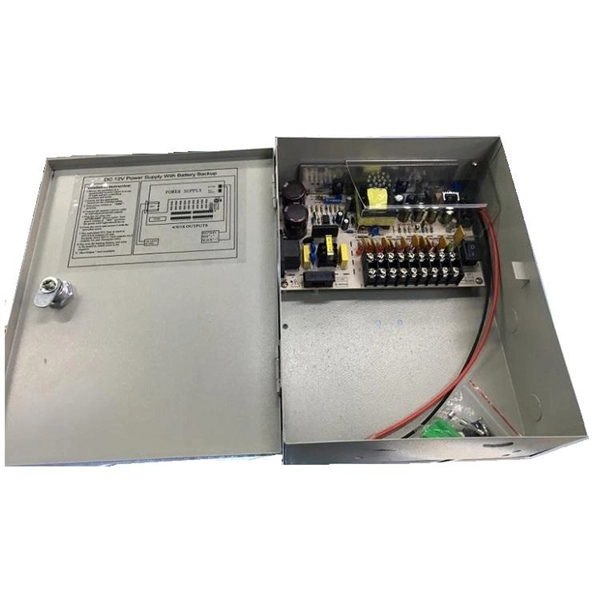
In this video, we'll show you how to connect an energy meter to a distribution board (DB) safely and efficiently. A residential electric meter box wiring diagram illustrates the connection between the utility service drop and the main breaker panel. It shows the hot wire entering the meter lugs, the neutral wire connecting to the neutral bus bar, and the essential ground wire linkage to ensure system safety. energy meter connection with distribution box How to Connect an Energy Meter to Your Distribution Box Easily Steps to Properly Connect Your Energy Meter to a Distribution Box. This prevents arc faults and ensures safety when modifying or inspecting current paths. Inside the service housing, line conductors from the utility feed typically enter through the. The wiring that links the utility company's service point to a home's electrical distribution system is the main service connection. This “meter to panel” wiring establishes the pathway for all incoming electrical power from the grid to the home. Whether you're an electrician or a DIY enthusiast, this guide will help you understand the basics of home electrical distribution. What is Distribution Board? Distribution board.
[PDF]

Practice good wiring: secure grounding, neat cable management, proper insulation, and correct wire gauge and breaker size. Include protection devices like breakers, fuses, and surge protectors—each circuit should have its own protection. Comply with standards: Follow NEC, IEC . Learn how to wire a distribution box step by step! This video shows real on-site footage of electrical installation, demonstrating safe and standardized wiring methods used by professionals. It serves as a central hub for distributing electricity throughout a building, ensuring that power is delivered safely and efficiently to all the required locations. Hey, in this article we are going to see the Single Phase Distribution Box Wiring Diagram and Connection Procedure. Whether you're an electrician or a DIY enthusiast, this guide will help you understand the basics of home electrical distribution. What is Distribution Board? Distribution board. Material preparation: Prepare the required circuit breakers, wires, wiring ties and other materials, and ensure that they meet the design drawings and installation requirements. Location determination: Determine the installation position of the circuit breaker according to the position of the. A distribution box is the heart of any electrical system. It takes the incoming power and safely distributes it to different circuits throughout your building. However, the key to.
[PDF]
The following figure shows a typical breaker box panel for 120V and 240V circuits. There are three wires entering the main panel from the energy meter viz: 1. Hot 1 or Line 1 = Black Color 2. Hot 2 or Line.
[PDF]

On the US market, a 5. 26 mm 2 (10 AWG) ground wire must be used, and in all other markets a 6 mm 2 must be used. Grounding of the units: Attach a ground wire from one of the threaded studs (A) at the bottom of the housing, to the mounting plate (B). Power from factory ground must be installed by a qualified electrician. Each DISTRIBUTION BOX and controller must be grounded. Whether you're a seasoned pro or just starting out, this comprehensive guide will give you practical. To define the technical specifications for the supply of Fibre Optic Overhead Ground Wire (OPGW) for installation on extra high voltage power lines, under the responsibility of Tasmanian Networks Pty Ltd (hereafter referred to as 'TasNetworks'). This standard applies to all OPGW purchased for. 4. FO-VC2 JOINT USE - VERICAL MIDSPAN CLEARANCES 48. FO-GB GROUNDING AND BONDING 49. FO-RI JOINT USE RISER. The requirement includes the design, supply, stringing and splicing of OPGW cable on 400KV, 220KV & 132KV Transmission Towers. This specification defines the design, material, performance and test requirements for fibre optic cable to support the fibre optic telecommunication needs. The work. IPMENT, STRUCTURES, ETC. IN ELECTRICAL STATIONS INCLUDING TRANSMISSION AND DISTRIBUTION SUBSTAT GR THAN 8 FT FROM THE FENCE. THE FENCE SHALL BE GROUNDED SEPARATELY FROM THE GRID UNLESS OTHERWISE NOTED ON THE A PROPRIATE PROJECT DRAWING. FOR FENC G O OUTSIDE CLEARANCE SPACING. SEE APPLICATION.
[PDF]

This phenomenon is known as the skin effect. The result is higher electrical resistance, energy loss, and reduced efficiency — particularly problematic for data transmission and high-frequency power applications. Through smart conductor stranding, manufacturers can reduce the. Defective products and waste products of bundled wire and stranded wire, the main problems are over-twisting, inner or outer single wire breakage, lack of strands, single wire or stranded wire surface abrasion, single wire dorsal strand, single wire peeling, scarring, brittle breakage, arching. This phenomenon is known as the skin effect. Through smart conductor stranding, manufacturers can reduce the impact of this effect. Causes of generation. Causes of. Understanding the diverse factors that can compromise cables—mechanical stress, environmental conditions, electrical anomalies, and more—empowers us to prevent, identify, and address issues promptly. By recognizing the importance of cables and the potential risks they face, we can ensure the. Both shielded and unshielded twisted-pair copper cable comes in either stranded or solid wire versions. There are plenty of considerations when it comes to choosing one or the other, including standards, environment, application, and cost.
[PDF]
