In this comprehensive guide, we will walk you through the step-by-step process of wiring outdoor outlets safely and effectively. 💡 Quick Answer: An outdoor electrical junction box is a weatherproof enclosure where electrical wires connect or split, required by code to protect connections from moisture, provide safe access for maintenance, and prevent electrical hazards in exterior applications. Properly wiring outdoor outlets enhances safety, functionality, and convenience. However, because outdoor electrical work involves. Installing an outdoor electrical panel box requires careful planning and execution. This guide covers everything you need to know for a safe installation. Understanding local electrical codes is paramount; these regulations ensure safety and compliance. Using the right tools, such as a voltage. Outdoor wiring faces harsher conditions than indoor installations as it is exposed to moisture, sunlight, and mechanical damage. Outdoor Receptacles (NEC 210. 9. An outdoor breaker box with integrated outlets is a specialized electrical assembly that serves as a weather-rated subpanel or load center. Designed for exterior use, it often features pre-wired receptacles directly on the enclosure. It takes the incoming power and safely distributes it to different circuits throughout your building. However, the key to.
[PDF]
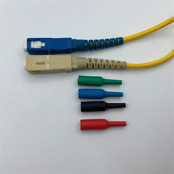
A fiber-optic splitter, also known as a, is based on a of an integrated waveguide power distribution device, similar to a The system uses an optical signal coupled to the branch distribution. The splitter is one of the most important in the link. It is an optical fiber tandem device with many input and output terminals, especially applicable to a passive optical network (,,,.
[PDF]

Circuit breaker wiring configurations involve organizing main switches, busbars, and branch breakers within a distribution box. Proper setups ensure balanced electrical loads, ground fault protection, and easy maintenance. Messy distribution boxes are dangerous and very hard to fix. This guide shows you how to organize circuit breaker wiring properly. You will learn to build a safe, efficient, and professional electrical system today. Location determination: Determine the installation position of the circuit breaker according to the position of the. The distribution board is the heart of every electrical installation. This guide covers split load vs dual RCD vs RCBO board configurations, circuit arrangement and allocation, BS 7671 labelling requirements, type testing under BS EN 61439, SPD installation, wiring best practice, and the common. Distribution panels, breaker panels, load center, and/or distribution boards—any name you call them, they're a key part of every electrical system. Wiring distribution panels serve as the central hub and nerve center, routing power from the main service feed to multiple circuits. When setting up. Hey, in this article we are going to see the Single Phase Distribution Box Wiring Diagram and Connection Procedure. It serves as a central hub for distributing electricity throughout a building, ensuring that power is delivered safely and efficiently to all the required locations.
[PDF]
Explore a comprehensive guide to residential electric meter box wiring diagrams, offering clear instructions for safe and efficient installation. A distribution box is the heart of any electrical system. It takes the incoming power and safely distributes it to different circuits throughout your building. However, the key to. Learn how to wire a distribution box step by step! This video shows real on-site footage of electrical installation, demonstrating safe and standardized wiring methods used by professionals. It has three categories: residential, commercial and industrial electrical distribution boxes, all of which play important roles in their respective electrical. Cleaning of the various PXBCM device housings should only be done with power and mains disconnected. A clean dry rag can be used to remove dust. No liquids should be used. Catalog Numbers Catalog Number DescriptionSuffix De- scription Notes PXBCM-MB Meter Base PXBCM-MMS-L09-A Meter Module Strip. full turn-key system solution backed with industry leading reliability and performance. Applications - The minimally invasive retrofit kit enables the opportunity existing remote power infrastructure cross arm, & wiring) providing the total cost of ownership. Failure to strictly adhere to the.
[PDF]

In this video, we'll walk you through the process of wiring a home distribution box with a detailed connection diagram. Correct wiring methods for circuit breakers within distribution boxes are fundamental to ensuring electrical safety and compliance with established codes. The distinction between 1P and 2P circuit breakers plays a pivotal role in determining the appropriate protection level for various circuits. This guide shows you how to organize circuit breaker wiring properly. You will learn to build a safe, efficient, and professional electrical system today. Circuit breaker wiring configurations involve organizing main switches, busbars, and branch breakers within a distribution box. Whether you're an electrician or a DIY enthusiast, this guide will help you understand the basics of home electrical distribution. more Welcome to our channel! In this video. Connection method: Each switch takes a wire from the incoming point and connects it to the incoming end of the switch, or uses parallel connection to reduce the difficulty of wiring. Wiring Direction: Wiring between the main circuit breaker and each branch circuit breaker in the box generally. A breaker box, also known as a circuit breaker panel, is an essential component of any electrical system. It is responsible for distributing electricity throughout a building, ensuring that each circuit receives the proper amount of power.
[PDF]

This AutoCAD DWG file includes a complete Single Line Diagram (SLD) of a Distribution Board, showing circuit breakers, wiring connections, and load distribution for lighting, power, and mechanical systems. An electrical panel box, also known as a breaker box or a distribution board, is a crucial component of any electrical system. It serves as a central hub for distributing electricity throughout a building, ensuring that power is delivered safely and efficiently to all the required locations. Whether you're an electrician or a DIY enthusiast, this guide will help you understand the basics of home electrical distribution. What is Distribution Board? Distribution board. Welcome to our channel @Electricalgenius In this video, we'll take you through a detailed step-by-step guide on wiring a home distribution DB (Distribution Board) box. A distribution board (also known as a service panel or breaker box) is a centralized collection of circuit breakers, fuses, and/or relays used to control and protect the wiring in a home. The diagram. To understand how a breaker box works, it is helpful to have a wiring diagram that shows the connections between the various components. At the heart of a breaker box is the main breaker, which controls the flow of electricity from the utility into the building. This breaker is connected to a.
[PDF]

Practice good wiring: secure grounding, neat cable management, proper insulation, and correct wire gauge and breaker size. Include protection devices like breakers, fuses, and surge protectors—each circuit should have its own protection. Comply with standards: Follow NEC, IEC . In this video, we'll walk you through the process of wiring a home distribution box with a detailed connection diagram. Whether you're an electrician or a DIY enthusiast, this guide will help you understand the basics of home electrical distribution. more Welcome to our. A distribution board (also known as a service panel or breaker box) is a centralized collection of circuit breakers, fuses, and/or relays used to control and protect the wiring in a home. The diagram of the distribution board's wiring shows exactly how each circuit is wired and connected. Choose the right box based on environment (indoor/outdoor), load capacity, and durability. Check for proper IP/NEMA ratings and material quality. Ensure safe placement: install in. The term “four wires” refers to three live wires and one neutral wire, designated as A|B|C|N|, with N representing the ground wire. The three live wires should be connected to the upper entry of the main switch in the explosion-proof distribution box, and the neutral wire should be directly.
[PDF]

Buyers typically pay a broad range for replacing a distribution box, driven by box size, amperage, wiring runs, and local labor rates. This article outlines the cost factors, price ranges, and practical budgeting advice for a U. Key cost drivers include panel amperage, indoor vs outdoor location, wiring length, and whether a full panel upgrade or rerouting is needed. Fiberglass 28 ft single sided stepladder is now loaded with new advanced features. Multifunctional Holster-top PRO keeps tools organized and safe on the ladder top. A magnetic strip and hardware. Nicaragua power strips and PDU power distribution units for surface mount, rack mount and general purpose applications. Multiple outlet power strips are manufactured in accordance to Nicaragua standards with agency approvals. Quality Nicaragua power strips, in stock, for standard duty applications. Distribution box cost encompasses various factors that influence the overall investment in electrical distribution systems. The price depends on electrical code upgrades, permit. Whether you're building a new home, remodeling, or simply need to upgrade your electrical system, having a reliable electrical box is essential. An electrical box, also known as a junction box, is a crucial safety feature in any electrical system. It serves as a protective enclosure for electrical.
[PDF]

In this article, we will discuss the wiring diagram for a typical 6 terminal junction box, which is commonly used in residential and commercial buildings for a variety of applications. Learn how to wire a distribution box step by step! This video shows real on-site footage of electrical installation, demonstrating safe and standardized wiring methods used by professionals. Wiring Direction: Wiring between the main circuit breaker and each branch circuit breaker in the box generally. In this guide, we'll break down everything you need to know to install a distribution box correctly and confidently. Choose the right box based on environment (indoor/outdoor), load capacity, and durability. Check for proper IP/NEMA ratings and material quality. Ensure safe placement: install in. It is the policy of the Company to serve all its customers in an orderly manner and assist in securing a more beneficial use of electricity. The “Xcel Energy Standard for Electric Installation and Use” contains the requirements and uniform standards necessary to achieve this policy. Uniform. An electrical panel box, also known as a breaker box or a distribution board, is a crucial component of any electrical system. It serves as a central hub for distributing electricity throughout a building, ensuring that power is delivered safely and efficiently to all the required locations. The 6 terminal junction box wiring diagram provides a visual representation of how the various wires and.
[PDF]
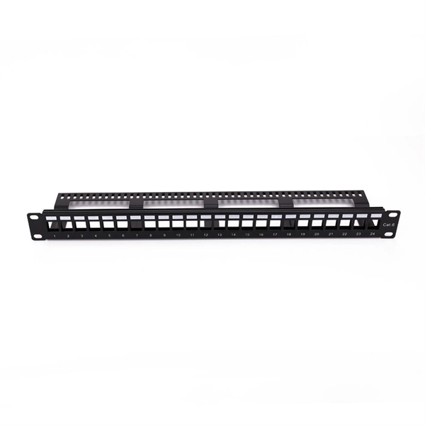
Splice boxes keep joints of fiber-optic cables safe from external stress and manage excess cable lengths. They are also referred to as Optical Termination Boxes. The GZR Series 19" Rack-mounted Terminal Box (Rail-based) is a functional component for optical fibre distribution frames or network integrated cabinets, offering fibre splicing, distribution, and tray storage. CAHORS offers complete solutions for FTTH distribution in residential. OTRANS provides professional, high-quality rack mount fiber patch panels (also known as fiber termination boxes) designed for modern data centers and network infrastructure. Our comprehensive range, from 1U to 4U standard 19-inch panels, offers scalable port densities (12 to 96 ports) to meet your. Distribution Cabinet Box – The Multi-Operator cabinet is a grouping module for fusion, coupling and connection of up to 48 fibers. Our boxes serve as a connection point for incoming and outgoing cables, providing cable termination, organization, and protection. GAO's box includes features such as cable. With the growing global deployment of Fiber-to-the-Home (FTTH) networks driven by the demand for ensuring high-capacity broadband services, mobile network operators (MNOs) face challenges of excessive energy consumption (EC) of wired optical access networks (OANs). This paper presents a.
[PDF]
The electrical box is made of 0. 5 mm cold-rolled steel, featuring high toughness, pressure resistance, and rust resistance;The shell has an epoxy polyester powder coating with good mechanical and leveling properties Whether for outdoor installations or indoor electrical. The electrical box is made of 0. These enclosures not only organize complex wiring but also protect sensitive. NAHMA PLC is a premier metal enclosure manufacturer in Ethiopia, specializing in high-quality sheet metal fabrication. We produce durable, standards-compliant enclosures designed to protect sensitive electrical and electronic components in any environment. From standard junction boxes to large. Waterproof and weatherproof junction box for all electronic installation works. Check each product page for other buying options. Price and other details may vary based on product size and color. This junction box has high water resistance up to IP67, high dust resistance, and is suitable for outdoor street light connection, communication wiring, airport, construction, mechanical equipment, outdoor solar equipment and so on. It can. Junction boxes by cape electric are made from halogen free fibre reinforced Polycarbonate (Outdoor) / Polystyrene (Indoor) materials which are available in IP65 Range for Outdoor / Indoor Application. IP68 Ranges of Junction Boxes are used in Extreme application such as underwater or soil.
[PDF]

This complete guide covers everything from identifying causes of failure to advanced repair techniques, drawing on the latest industry standards and innovations. A fiber termination box is the standard instrument used in fiber optic networks to connect, secure, and protect optical fibers at the terminating point. Proper installation and maintenance of FTBs are essential to ensure the reliability and performance of the network infrastructure. Before. By understanding these key elements and following the outlined steps, you can effectively repair fiber optic cables and maintain the high-performance network necessary for today's demanding communication needs. Whether you're a network technician, IT professional, or telecom operator, you'll find practical steps, tools, and tips to restore. FTTP or fiber To The Premises applications have reinforced the importance of reliable and stable fiber optic terminations. Good quality fiber laying and termination systems help achieve minimal back reflection and low signal loss. They also feature resistance to moisture, impact, chemical exposure. A fiber optic distribution box, also known as a fiber optic terminal box or fiber optic termination box, is a device used to connect and manage fiber optic cables in a network. The distribution box provides.
[PDF]

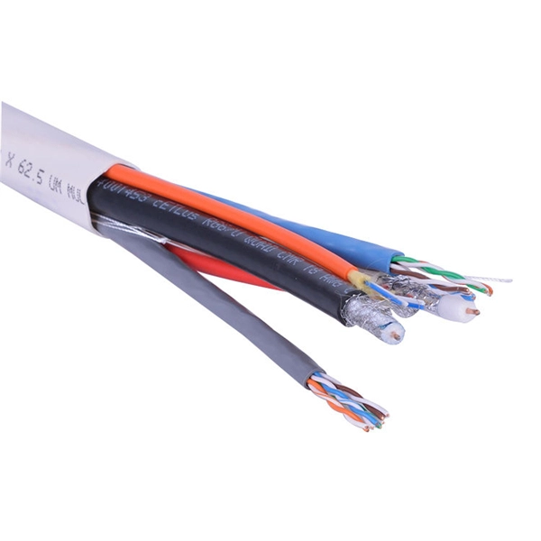
Optical Network Terminals (ONTs): Often called "fiber boxes," ONTs are located inside homes and connect the fiber optic cable to the internal network. They receive the optical signal from the external fiber optic cable and convert it into a usable signal for home networking equipment. A fiber optic junction box, also known as a fiber optic distribution box or termination box, is a protective enclosure that facilitates the connection and management of fiber optic cables. It serves as a central point for organizing and distributing optical fibers, ensuring efficient connectivity. A Fiber Terminal Box (FTB) is a customer-side termination and distribution device used at the end of the optical network. Key Functions Typical Applications ZION FTB Highlights In essence: The Fiber Terminal Box is an end-user termination device for small-scale distribution. ■ What Is a Fiber. Fiber junction boxes play a crucial role in the organization, protection, and distribution of fiber optic cables in various applications, including telecommunications, data centers, and industrial networks. Primary Purpose: Its core function is to provide a secure, protected location. To handle a large number of optical fibers with lower cost and higher flexibility, various optical junction boxes are widely used to connect and arrange optical fibers. The distribution box provides.
[PDF]
