
For busbar sizing, the primary references are IEC 61439 (for low-voltage switchgear and controlgear assemblies) and IEC 60287 (for current-carrying capacity of cables). IEC 61439 is a standard developed by the International Electrotechnical Commission (IEC) that covers design verification for low-voltage electrical products and assemblies. The IEC 61439. With SIRIUS, SENTRON, SIVACON and ALPHA, we offer an innovative portfolio for standard-compliant and demand-oriented applications. Efficient engineering tools and innovative cloud-based solutions can be flexibly tailored to individual requirements. com/system-certificates/ep). The. 7 cycles of 24 h each to salt mist test according to IEC 60068-2-11; (Test Ka: Salt mist), at a temperature of (35 ± 2) °C. The test shall be carried out according to IEC 60068-2-2 Test Bb, at a temperature of 70 °C, with natural air circulation, for a duration of 168 h (7 days) and with a recovery. The International Electrotechnical Commission (IEC) issues globally accepted standards that promote safety and efficiency in electrical engineering. Standard sizes and ratings and a complete line of components allow each system to be tailored to suit the requirements of each application, while at the same time provide the.
[PDF]

The price of FRP trays can range from $10 to $50 per meter, depending on the specifications such as size, design, and environmental factors. Cable trays are vital in electrical installations, providing secure pathways for power, communication, and control cables across residential, commercial, and. Using 3/4" conduit for each cable at. 34/ft using 20 ft sections in tray and 10 ft sections for the drop. 21/ea for every 6 ft of cable for the drops and conduit couplers at. Understanding the key factors that influence their pricing helps engineers, contractors, and. This guide covers the critical steps, from selecting the right electrical cable tray and performing accurate cable fill calculations to managing a safe cable pull through and ensuring all bonding and grounding requirements are met. For licensed electricians, mastering these principles is essential. Market context (at-a-glance): Industry analysts valued the global low voltage wire & cable market at roughly USD ~ 145. 7 billion in 2024 and is projected to grow at a CAGR of 7. 2% from 2025 through 2034. Nearly 70% of new homes are now built with low voltage systems (industry estimate) meaning that. Ladder type cable trays are built for heavy-duty routing. In power-heavy areas, they prevent failures that would be far more expensive than the tray itself. Perforated cable trays sit in the middle. They cost less than ladder.
[PDF]
In electric power distribution, a busbar (also bus bar) is a metallic strip or bar, typically housed inside switchgear, panel boards, and busway enclosures for local high current power distribution, transmission, or switching substations. They are also used to connect high voltage equipment at electrical switchyards, and low-voltage equipment in battery banks. They are generally uninsulated, and h. Design and placementThe busbar's material composition and cross-sectional size determine the maximum current it can safely carry. Busbars can have a cross-sectional area of as little as 10 square millimetres (0.016 sq in), but. • – Data transfer channel connecting parts of a computer• – Low resistance electrical conductor for high current transmission and distribution• – Modular approach t. • Elmore, Walter A. (1994). Protective Relaying Theory and Applications. Marcel Dekker.• Paschal, John (2000-10-01). Electrical Construction & Maintenanc.
[PDF]

Perform a dielectric strength test to check the insulation properties of the busbars under high voltage conditions. The Partial Discharge test is crucial for determining long-term part. A busbar protection must be capable of clearing all phase-to-earth faults, and in the case where they can occur, phase-to-phase faults. Policy regarding fault clearance times required from busbar protection varies from utility to utility. Due to the fact that the short-circuit levels of bus bars. Early detection of cracks is crucial for preventing. Check the mechanical. The voltage of the faulted phase decreases (in case of incomplete grounding) or drops to zero (in case of solid grounding). In stable grounding, the. Busbar Differential Protection Definition: Busbar differential protection is a scheme that quickly isolates faults by comparing currents entering and leaving the busbar using Kirchoff's current law. Current Differential Protection: This protection method connects CT secondaries in parallel and. That's based on air insulated buswork well above your head and a reasonable set of remote zone 2 times. I agree with you as chances of surviving a bus fault is practically non existent at 110/220kV regardless if its cleared in ~100ms via busbar prot scheme or via remote end in zone 2 times of.
[PDF]
Voltage level: Industrial facilities often use multiple voltage levels (such as 1kV, 10kV, 400V), and it is necessary to ensure that the cable distribution box layout separates different voltage systems to avoid interference. A distribution box is the heart of any electrical system. It takes the incoming power and safely distributes it to different circuits throughout your building. Whether in a home or an industrial facility, this box keeps your electrical setup organized, functional, and efficient. However, the key to. Design requirements for low voltage distribution boxes cover NEC, IEC, and safety standards to ensure reliable, compliant electrical installations. You must make safety your top priority when working with low voltage distribution boxes. Protection requirement: According to the fault risk (such as short. For Branch Circuits (the conductors spanning from the final overcurrent device or breaker to the actual outlet, light fixture, or equipment), NEC Informational Note No. 4 recommends a maximum voltage drop of 3%. This ensures that the device at the end of the line receives at least 97% of the panel. For distribution boxes that handle only lighting circuits or small power loads, if the incoming wire size is less than 10 square millimeters and the number of circuit switches is fewer than 20, the width of the box should be calculated by summing the width of the switches and adding an additional.
[PDF]
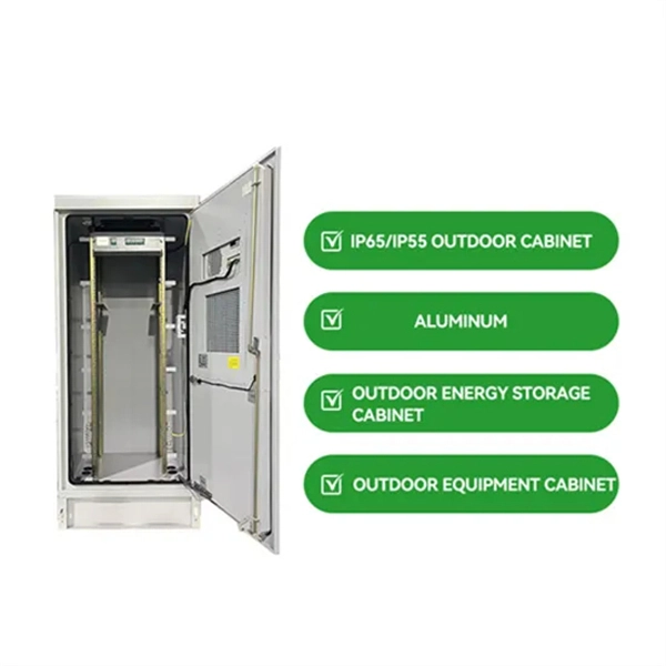
Find Prefabricated Telecom Shelter manufacturers, suppliers, dealers & latest prices from top companies in India. We are the first Indian company to provide 'Ready to Erect' Telecom Shelters in India with in-house Design, Engineering, Manufacturing and Erection / Installation capability all across India for efficient and cost effective operations of telecom equipment. (Dust Weather proof Insulated Cabin for. Prominent & Leading Manufacturer from Greater Noida, we offer portable prefabricated shelters and puf insulated telecom shelter. Our broad scope of pre-assembled covers incorporates a wide exhibit of Portable Telecom Shelters. Designed for rapid deployment and exceptional durability, our portable shelters are ideal for various applications, including the telecom and railway. Leading Manufacturer of prefabricated telecom shelters from Faridabad. Constructed with durable materials, these shelters ensure reliable performance.
[PDF]

They take power from one main source and safely channel it to multiple circuits within electrical enclosures like switchgear, panelboards, and distribution boards, replacing many individual cables. Busbars are fundamental workhorses in power distribution. In electric power distribution, a busbar (also bus bar) is a metallic strip or bar, typically housed inside switchgear, panel boards, and busway enclosures for local high current power distribution, transmission, or switching substations. They are also used to connect high voltage equipment at. Current Rating: Each busbar is rated for a specific current capacity to match system requirements. This setup allows busbars to distribute large currents safely, making them vital in high-power applications. Busbars come in various forms, each suited to different applications depending on the power. Whether it's a high-voltage substation or a low-voltage battery bank, busbars ensure seamless power flow, connecting incoming and outgoing feeders effortlessly. They're not just about distributing electricity; they're about doing it faster, and safer. With modern systems demanding higher efficiency. A busbar is essentially a strip or bar of conductive metal, usually copper or aluminum. In simple terms, a busbar is a common node where multiple incoming and outgoing circuits connect. Typically made from conductive materials like copper, aluminum, or brass, busbars.
[PDF]

12KV High Voltage Epoxy Resin Through Wall Bushing for Busbar TG4-12-140x200 , made from high-quality materials with excellent craftsmanship, customisation available. Please contact us for more information. XBRELE's Epoxy Wall Bushings (also known as Through-Wall Insulators) provide reliable electrical isolation for busbars passing through grounded partitions. Featuring TG3 (KYN28) and Gas-Tight (GIS) series, molded via APG technology for zero partial discharge. Designed for high mechanical bending. Our medium voltage through-wall bushings play a critical role in electrical systems by providing reliable separation between busbars and surrounding components. We design these epoxy bushings specifically for medium voltage applications, ensuring they isolate conductors—such as quarter-inch thick. Our bushings for wall applications are specifically designed to be mounted on the wall or tank of electrical power equipment. 5 is a cast epoxy resin combined bushing busbar wall crossing device used in medium and high voltage power equipment. This equipment is usually used in substations and industrial distribution systems to achieve insulation and sealing functions when cables or busbars pass through walls. Description:Wall busing is a type of electrical equipment used to connect high-voltage cables to devices such as circuit breakers and transformers. Resistant to dirt and moisture, the epoxy.
[PDF]
In , a busbar (also bus bar) is a metallic strip or bar, typically housed inside,, and for local high current power distribution, transmission, or switching substations. They are also used to connect high voltage equipment at electrical switchyards, and low-voltage equipment in. They are generally uninsulated, and have sufficient stiffness to be s.
[PDF]

Headquartered in Fort Wayne, Indiana, GMS Distribution distributes and sells its products in the United States and Canada. 30 Amp Portable Power Box GMS's Portable Power Distribution Centers have been designed to be the easiest power box you will ever plug in. GMS is focused on the. Our products boast customizable materials and dimensions, ensuring a tailored experience. With a range of materials to choose from and the ability to adjust sizes to your liking, our offerings are designed to meet your unique needs and preferences. American Distribution Boxes are made of high-density polyethylene for years of dependable use. They are non-corrosive, strong, and lightweight for easy handling. Inlet and outlet elevations are positioned to provide equal distribution and meet most local codes. Twist and lock 4” pipe seals and. It is the high-voltage core unit of the American box type transformer, integrating high-voltage load switches, fuses, etc., with a voltage of mostly 15kV. PREMIUM CONSTRUCTION POWER DISTRIBUTION BOX: Crafted by WESTERN, the 6506TLSX Temp power box features a durable blend material for long-lasting performance in demanding environments. ATEK Distribution supplies professional-grade electrical boxes for residential, commercial, industrial, and government projects nationwide. As a certified SDVOSB with 28+ years of experience, we carry every box type you need — correctly specified, fully documented, and ready to ship. Whether you're.
[PDF]

This article provides a detailed technical comparison between fiber optic and copper cables, offering a clear perspective for engineers, network architects, and procurement managers. The core distinction between the two technologies lies in the physics of data. However, the exponential growth in data demand has positioned fiber optic technology as the superior alternative for performance, scalability, and future-readiness., 10G/25G/40G/100G and beyond depending on optics and reach). Copper Ethernet scales too, but practical limits are lower and depend. The two main options are fiber optic cables and copper cables, each with its own advantages and drawbacks. Fiber optic cables are praised for their high performance and scalability, while copper cables remain a cost-effective choice, especially for budget-conscious projects and older systems. Copper wire is more susceptible to interference and has limited data capacity, making optical fiber the preferred choice for modern high-speed. Optical connectivity, utilizing fiber-optic technology, has emerged as the superior choice for modern networking, offering unparalleled performance, reliability, and scalability. For example, a typical 10 Gbps copper Ethernet link (such as Cat 6A) over 100 meters can consume approximately 5 to 8+.
[PDF]

Compare fiber optic and copper Ethernet cables across speed, distance, cost, installation difficulty, and use case metrics. Use the interactive scenario selector to find the right medium for your specific network — all processed locally in your browser. PoE Required?. The core difference between fiber optic and copper cables lies in how they carry data. One uses light, the other electricity—and that distinction shapes everything from speed to signal integrity. Fiber optics transmit data as pulses of light through ultra-thin strands of glass or silica. Both technologies can deliver high-speed connectivity, but they behave differently under real-world constraints such as. However, the exponential growth in data demand has positioned fiber optic technology as the superior alternative for performance, scalability, and future-readiness. This article provides a detailed technical comparison between fiber optic and copper cables, offering a clear perspective for. Fiber optic tends to be the more premium solution, while copper wiring is far more common, but why is that? What are the differences between these two cable types, and why might you want to pick one over the other? Here's everything you need to know about fiber vs. copper cables, to help you pick. Several factors are converging to drive the switch from copper to fiber – and cost is a big one. A recent investor presentation by AT&T claimed that fiber was 35% less costly to maintain than copper.
[PDF]

Since there are two sections, separated by a circuit breaker, the fault on one section does not interrupt the other section of the bus. Maintenance of the bus section can be done individually, without affecting other. Variants include a sectionalized single bus, where one or more bus couplers divide the bus into segments to limit the extent of outages. Layout: one energized bus; each feeder/generator/transformer bay has a breaker and isolators. Sectionalization adds a bus coupler breaker and isolators to split. The relevant standard for High Voltage Switchboards is 62271-200. This standard covers High Voltage Switchboards with voltage levels above 1kV and up to 52kV. It is also used in small outdoor stations having relatively few outgoing or incoming feeders and lines. shows the single bus-bar system for a typical power station. The generators, outgoing lines and. Bus-bars are copper rods or thin walled tubes and operate at constant voltage. We shall discuss some important Bus Bar Arrangement in Power Station and sub-stations. All the diagrams refer to 3-phase arrangement but are shown in single-phase for simplicity. Single Bus-bar System: The single. This is a single bus system, with additional circuit breaker and isolators, making two different sections of bus, hence called a single bus system with bus sectionalizer. A busbar is a metal bar, usually made of copper or aluminum, that carries electricity inside switchgear.
[PDF]


