They are designed to split unpolarized light at a specific Reflection/Transmission (R/T) ratio with unspecified polarization tendencies. A beam splitter or beamsplitter is an optical device that splits a beam of light into a transmitted and a reflected beam. It is a crucial part of many optical experimental and measurement systems, such as interferometers, also finding widespread application in fibre optic telecommunications. This division allows for the simultaneous analysis or utilization of the light's properties along two separate paths. The device is purely. Transmission and Reflection by. In addition to the task of dividing light, beamsplitters can be employed to recombine two separate light beams or. Explore the precision, applications, and design principles of beam splitters, essential for advancements in scientific research and technology. With WDS, a single X-ray energy – monochromatic X-rays – are counted at any given time. 19511; JEOL L-Value table2; CAMECA® SXFiveFE brochure3; Oxford Instruments Wave brochure4; Thermo ScientificTM NORANTM IbeX5). Unlike conventional beam splitters, PBSs ensure that the resulting beams are both linearly.
[PDF]

Where traditional computer chips push electrons through copper wires, silicon photonic chips guide photons (particles of light) through tiny channels called waveguides etched into the same silicon material. The result is faster data transfer, less heat, and dramatically lower. Silicon photonics is a technology that uses light instead of electrical signals to move data through circuits built on silicon chips. The silicon is usually patterned with sub-micrometre precision, into microphotonic components. These operate in the infrared, most commonly at the 1. More simply, while traditional semiconductors like CPUs, GPUs, and SoCs in computers and smartphones are silicon-based integrated circuits, silicon. Silicon photonics is a type of integrated photonics that utilizes silicon-based fabrication processes to create optical chips. Thereby it opens a route towards very advanced PICs with very high yield and low cost. More precisely, silicon photonics. Photonic crystals with extremely high quality cavities. Waveguide losses dominated by scattering. Use better litho + etch CROSSINGS. Optional undercut to lower thermal leakage. ELECTRO-OPTIC EFFECT IN SILICON: INJECTION VS.
[PDF]

It operates by splitting incoming light into one or two beams, with one or more beams passing through the optical element and one or more beams being redirected at an angle away from it. This tool is crucial for various applications, including lasers, heads-up displays, and other. Beamsplitters are fundamental components in optical engineering, serving to precisely divide a single input beam of light into two distinct output beams. This division allows for the simultaneous analysis or utilization of the light's properties along two separate paths. It is a crucial part of many optical experimental and measurement systems, such as interferometers, also finding widespread application in fibre optic telecommunications. In its. Beamsplitters are optical devices able to either split an incident light beam into two separate beams or combine two incoming beams from distinct angles into a single output. These versatile tools can split both laser and regular light, depending on the application in question. Image Credit: Shanghai Optics Most plate beamsplitters are. Explore the precision, applications, and design principles of beam splitters, essential for advancements in scientific research and technology. Beamsplitters are often classified according to their construction: cube or plate.
[PDF]

They are the bridge between fiber optic cables in the field and the equipment or patch panels that manage them. By combining factory-installed connectors with spliced bare fiber, pigtails ensure that network installers can create fast, reliable, and cost-effective terminations. Fiber pigtails are simple in appearance, yet essential in function. This unique design is the key to seamless integration with a variety of optical devices, ensuring signals traverse with. Executive Summary: A fiber optic pigtail is one of the most commonly specified yet least understood components in structured cabling. Get the wrong connector type, the wrong polish, or skip proper fusion splicing technique—and you're looking at elevated signal loss, increased back reflection, and a. A pigtail fiber indicates a short length of optical fiber cable that has a pigtail connector (for example, SC, FC, ST, LC, etc. ) fitted on one end and the other end undressed (for connection through fusion or splicing) to the main fiber optic cable. This essential function of pigtail fiber is. Fiber optic pigtails are short, single, or multi-strand pieces of optical fiber cables with a connector on one end and exposed fiber on the other end. But what exactly is a pigtail and why do you use it? In this article, we explain why they are important and which pigtail connector you should choose, with a focus on SC and LC pigtails. What is a pigtail? A pigtail is used to.
[PDF]
A 24-port patch panel is a networking device that allows for the organization and management of incoming and outgoing network connections. It acts as an interface between different devices such as computers, switches, and routers, allowing for easy connectivity and communication. This guide explains how to use a 24-port patch panel to manage copper and fiber cabling in a small LAN, how to choose between different patch panel types, how to design your cabinet layout, and why a patch panel is still irreplaceable in 2026. What is a Patch Panel and Why it Matters in 2026? A. Choosing a 24-port patch panel is crucial for efficiency. Learn how it enhances network capabilities. Typically, patch panels are available in a huge number of port densities from 12. In this article, we will define what a patch panel 24 port is, explain its purpose, and discuss why it is a crucial component in organising network cables. A patch panel 24 port is a device used in network cabling to connect and organise multiple network cables in one central location. It is a. Choose a 24-port patch panel when you care about clean labeling, comfortable “finger room,” and fast moves/adds/changes—especially if technicians touch the rack often and you want straightforward port-to-port mapping (Panel 01–24 ↔ Switch 01–24). Choose based on port density, cabinet space.
[PDF]
Fiber optic adapters play a vital role in modern optical communication systems by enabling seamless connections between fiber optic cables. These small yet essential components ensure efficient data transmission, reduce signal loss, and maintain system integrity (1). In this article, we'll explore. Explore the essentials of fiber optic adapters, their types, benefits, selection, maintenance, and their role in future tech. They serve as interfaces for connecting fiber optic cables, facilitating. Fiber optic adapters are small but essential components that ensure precise alignment between connectors. Using the wrong type or neglecting cleaning can lead to signal loss and unstable connections., two fiber connectors) such that light can reliably pass from one to the other with minimal insertion loss and maximum return loss. Though fiber optic adapters are small accessories often ignored by technicians, they play a vital role in fiber telecommunications, connecting fiber optic cables and connectors. This article discusses their purposes, features, types, and how to choose and clean them. Most fiber optic connectors are composed of.
[PDF]

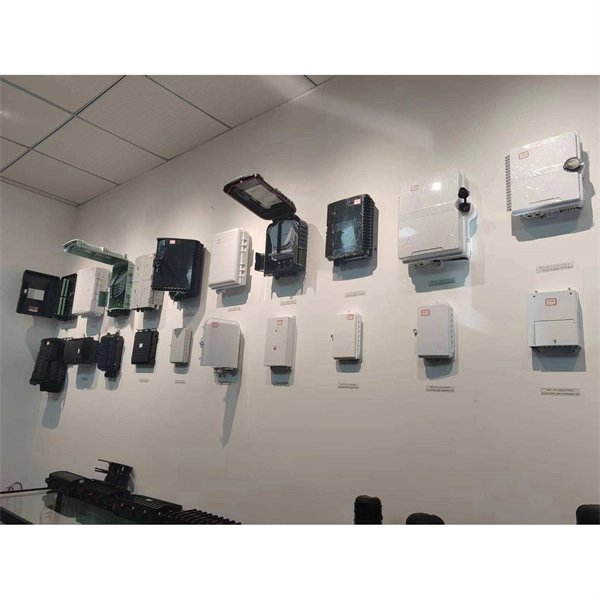
Fiber optic terminal boxes provide functions such as input, branching and splicing of optical fiber cables. Through the connectors and splicing boxes in the terminal box, optical fibers can be quickly connected and repaired. Serving as a critical connection point, FTB facilitates the termination, splicing, or connection of fibers from various cables to other network devices such as switches, routers, or Optical Network Terminals (ONTs). It aids in splicing, splitting, storing, and managing fibers within the appropriate. The optical fiber terminal box is the terminal joint of an optical cable, one end of which is an optical cable, and the other end is a pigtail, which is equivalent to a device that splits an optical cable into a single optical fiber. A fiber pigtail is a specific hardware connection used for cable termination. It is a small enclosure that can house and protect the fiber optic cables, splices, and connectors. The optical fiber termination box and optical fiber splice box serve distinct purposes and are not interchangeable.
[PDF]
Optical cable junction boxes play a crucial role in connecting and protecting optical fibers, directly influencing the quality and lifespan of optical cable routes. Optical cable splice boxes protect the splicing parts of optical fibers from various hazards, such as water seepage due to adverse. Optical cable junction boxes play a crucial role in managing and organizing fiber optic networks. It serves as a termination point for fiber optic cables, providing protection and distribution of the optical fibers while ensuring efficient signal transmission. Utilizing an optical junction box can significantly enhance your. Optical cable splice box is a popular name, its scientific name is optical cable splicing box, also known as optical cable splicing package, optical cable splicing package and gun barrel. These boxes are designed to house and protect fiber optic splices and terminations, ensuring that the delicate fibers are safeguarded from.
[PDF]

The Israeli cable trays market is a critical component of the nation's industrial and construction infrastructure, serving as the backbone for organized and secure cable management across diverse sectors. As of the 2026 analysis, the market is characterized by steady demand driven by sustained. A cable tray is an organized support structure designed to secure and route these insulated electrical cables. It acts as a dedicated pathway for power distribution and data transmission, often supporting cables hidden behind walls or above ceilings. People use them in many buildings and work places to give cables a steady place to run. Cable trays come in different types: Materials: They can be metal (like steel with a coating, or stainless steel), plastic (like. In the electrical wiring of buildings, a cable tray system is used to support insulated electrical cables used for power distribution, control, and communication. When properly selected and installed, cable trays simplify routing, improve accessibility, and support future expansion while. Metal cable trays are widely used in demanding industrial settings to support, organize, and protect extensive cabling systems, ensuring efficient and safe power and data distribution. Their robustness and adaptability make them essential in sectors where conditions can be extreme, compliance with.
[PDF]
In , a busbar (also bus bar) is a metallic strip or bar, typically housed inside,, and for local high current power distribution, transmission, or switching substations. They are also used to connect high voltage equipment at electrical switchyards, and low-voltage equipment in. They are generally uninsulated, and have sufficient stiffness to be s.
[PDF]
A fiber-optic sensor is a that uses either as the sensing element ("intrinsic sensors"), or as a means of relaying signals from a remote sensor to the electronics that process the signals ("extrinsic sensors"). Fibers have many uses in. Depending on the application, fiber may be used because of its small size, or because no is needed at the remote location, or because many sensors can be along the length of a fiber by using light wavelength shift for.
[PDF]

The fiber optic cable core is the physical glass medium that transports optical signals from an attached light source to a receiving device. The light is transported along the optical fiber via its smallest and most crucial component, which is called the core. The modern digital world relies heavily on fiber optic cables, which serve as the high-speed backbone for global communication. Professionals in telecommunications, data centers, and network infrastructure must understand the core functions and why they are fundamental to their fiber optic. A fiber optic cable consists of five basic components: the core, the cladding, the coating, the strengthening fibers, and the cable jacket. When searching for a fiber optic cable, we need to pay attention not only to the connectors, such as SC to ST fiber cable, LC to SC fiber patch cable, or SC to. The reason is that cores are basically hidden components located that receive the light signals. Don't worry, in this guide, we'll discuss in detail what the fiber optic core is and its role in data transmission. Moreover, we'll also explore the different types of fiber optic cores available as. The core of a conventional optical fiber is the part of the fiber that guides the light. It is a cylinder of glass or plastic that runs along the fiber's length. The core is surrounded by a medium with a lower index of refraction, typically a cladding of a different glass, or plastic.
[PDF]

An elevator data communication system is configured to communicate between a plurality of elevator systems and a datacenter remotely located from the plurality of elevator systems. WAN – Wide area network is similar to a LAN but is not limited to a single location. It can also consist of several LANs which are interconnected. Usually, it is the only way how to contact the outside world and get help when you are trapped in the elevator. But many changes and exciting new challenges are coming in the field of elevator. “THE LONGEST RUNNING PUBLICATION FOR THE VERTICAL TRANSPORTATION INDUSTRY SINCE 1953. ” Open and standard communication protocols are vital for interoperability in building automation and elevators. The OSI seven-layer model frames protocol design but compliance alone does not guarantee. Elevators are essential in most modern buildings, but they need communication systems that meet code requirements. Here's how new features are making compliance easier—and delivering a new revenue stream. More sophisticated and effective communication solutions are needed to manage the increasing. Technical systems are, in general, becoming ever more complex. Electronic systems – usually equipped with tiny embedded microprocessors – are implementing new functions, increasing convenience or improving system safety and reliability.
[PDF]