Unlike traditional metal-style reels, MARS is a lightweight, modular system constructed of an impact modified polymer that is easily transported. It is ideal for applications where cable needs to be deployed and reeled in quickly and stored efficiently. OCC's Modular Advanced Reel System (MARS ®), the industry's first lightweight cable deployment reel system, is designed specifically for the demanding needs of harsh-environment fiber optic installations. The dual take-ups are designed to work independently from line controls, therefore providing an easy adaptation and a fast plug & play installation to any line.
[PDF]

Cable tray support quantity can be calculated using a simple formula: Support Quantity = Total Length ÷ Support Spacing + 1 20 ÷ 2 + 1 = 11 supports In a typical project, a 20-meter cable tray with 2-meter spacing requires 11 supports. This article explains the principles, methods, and practical examples for calculating cable tray support quantity. Ensure NEC compliance, estimate wire length/weight, calculate deflection, and generate hardware BOMs for bends, tees, and reducers. Ideal for electrical contractors and engineers. The. This guide provides a comprehensive approach to calculating cable tray loads, considering various factors such as cable weight, tray weight, environmental influences, and safety factors. Classification of Loads Cable tray loads can be classified into the following categories: Dead Load (G): This. This page also guides to determine the appropriate distance between supports for the load, based on number of cables, cable tray size, and bracket type. Wire Mesh Cable Tray Fill Ratio = Cross section of cable / Cross section of tray According to NEC 392. 9 (B), when using ventilated tray with multi. The National Electrical Code (NEC) covers many aspects of cable tray supports and fittings. The National Electrical Code is a set of principles designed to promote public safety and welfare, as well as safeguard public health by regulating the design and operation of electrical facilities and.
[PDF]
The formula for calculating electrical box size is: [ BS = (N times D) + A ] Where: ( BS ) is the box size in cubic inches. ( N ) is the total number of conductors. Article Summary: Calculating the correct junction box size per the NEC 2023 involves a process known as a “box fill calculation,” primarily governed by NEC Article 314. This count includes each conductor. Get the exact dimensions you need for a production quote. How It Works: Enter Your Product Details: Input your item's length, width, and height. Set Your Quantity: Tell us how many items you want to pack in each carton. ( A ) is the volume allowance for any device or fitting. How do I calculate box fill fast? This electrical box fill calculator (or in short, box fill calculator) will help you determine the total box fill volumes you will need to meet so that each of your electrical utility boxes will pass the National Electrical Code®. In this calculator, you will. Determine the proper junction box size for your electrical installation by calculating volume requirements, fill percentages, and ensuring compliance with electrical codes and safety standards.
[PDF]

Use this cable tray sizing calculator to check fill %, select tray size, and comply with IEC 61537 & NEC 392 with formulas, example and checklist. Our free calculator helps you determine the correct tray size based on NEC and IEC standards. Follow these simple steps: Define Tray Dimensions: Enter the width and depth of your planned cable tray (in mm or inches). Select Fill Standard: Choose 40% for power cables (NEC compliant) or 50% for. The right cable tray sizing calculator helps engineers turn cable schedules into a verified tray width and fill check before material ordering and site installation. IEC 61537 covers cable tray and cable ladder systems for the support and accommodation of cables, while NEC Article 392 governs cable. Calculate cable tray fill ratio, weight loading, and derating factors for multi-standard compliance. This calculator features an interactive interface with advanced visualizations. Open the full calculator for the best experience. Save your cable tray sizing calculator results as branded PDF. Size conductors installed in cable tray with NEC 392, NEC 310. 16, tray fill, ampacity adjustment, voltage-drop checks, grounding, and IEC design cross-checks. How to find. A 12 in ladder tray loaded to 4 in depth has 48 sq in of tray area; with 24 #12 THHN conductors at 0. 0133 sq in each, the screen is about 0. This page is a preliminary cable-tray occupancy screen for early layout work. It adds cable planning area, compares.
[PDF]

The formula used to calculate cable tray capacity is: Cable Tray Capacity = (Tray Width × Tray Depth × Fill Ratio) / Cable Cross-sectional Area Where: Tray Width is the internal width of the cable tray in meters (or millimeters). Using our advanced cable tray load calculator is simple and ensures your electrical installation meets structural and safety standards. Follow these steps to generate your accurate Bill of Materials (BOM) and engineering report: Step 1: Define System Specifications: Select your cable tray type. Wire Mesh Cable Tray Fill Ratio = Cross section of cable / Cross section of tray According to NEC 392. 9 (B), when using ventilated tray with multi conductor control cable, the sum of the cross sectional areas shall not exceed 50 percent of the interior cross section of the cable raceway / tray. We independently provide precision steel tools, calculators, and expert resources for steel, metalworking, construction, and industrial projects. I'm here to tell you, it's simpler than you might think, and it makes a huge difference. This guide will walk you through how to work out those loads. An overloaded cable tray can lead to structural failure, causing damage to cables and potentially resulting in costly downtime and safety hazards. Divide this by the cross-sectional area of a single cable to find the.
[PDF]

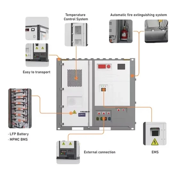
The use of locking cabinets with advanced steel and tamper-resistant designs utilizes physical barriers to limit access to sensitive materials, making them harder to reach for unauthorized individuals. This pressure can cause the gap below server cabinets, which is often 2” or more, to become an air stream between hot and cold aisles. The resulting mix of air reduces the effectiveness of a containment solution. The Cool Shield Magnetic Cabinet Skirt provides an easy fix for this issue. These. Commercial environments have evolved as technology advances, and having a robust cabling infrastructure is crucial for scalability, minimising downtime, and enhancing productivity. Educational institutions are increasingly adopting smart technologies and cloud-based resources, so the foundation of. Many network devices are stored in the cabinets. In order to meet the normal operation of these devices in the cabinets, when the computer room cabinets are full of various cabinets and devices, we need to consider how to place the network cabinets? 1. Network cabinet placement skills (1) Before. A network cabinet is defined as a physically enclosed compartment built to store networking gadgets like patch panels, modems, switches, and a multitude of cables. Network cabinets support large, modular network switches by providing additional space for cable management and side-to-side airflow solutions. Networking cabinets tend to have.
[PDF]

It's called a breaker box, and even though it might not look very exciting on the outside, what's behind that little door is the heart of your home's electrical system. Bottom Line Up Front: Your home's distribution box (electrical panel) is typically located in the basement, garage, utility room, or mounted outside near your electrical meter. To find it quickly, look for a rectangular gray metal box about the size of a medicine cabinet, often positioned close to. Electrical panel boxes, aka breaker boxes, can be on a wall in an out-of-the-way area of your home. You can find electric panels inside cabinets, behind refrigerators, or inside clothes closets in older homes. Current National Electrical Codes (NEC) allow none of these locations. Electrical panels. The electrical panel is the central hub that distributes electricity throughout the house. Knowing where to find your electrical panel in your home helps in case of emergencies and routine maintenance. Panels are commonly found in garages, basements, utility rooms, and outdoor walls. Understanding how your electrical panel works can help you troubleshoot issues, perform basic maintenance, and know when to. When something electrical goes wrong in your home—like a tripped circuit or sudden power outage in one part of the house—most people instinctively head to that gray metal panel, often hidden in a basement, utility closet, or garage. Having the breaker box.
[PDF]

The formula for calculating electrical box size is: [ BS = (N times D) + A ] Where: ( BS ) is the box size in cubic inches. ( N ) is the total number of conductors. ( A ) is the volume allowance for any device or fitting. This electrical box fill calculator (or in short, box fill calculator) will help you determine the total box fill volumes you will need to meet so that each of your electrical utility boxes will pass the National Electrical Code®. In this calculator, you will learn: How to use electrical box fill. Choosing the correct electrical box dimensions is essential for safe wiring, code compliance, and long-term reliability. Whether you are installing outlets, switches, lighting fixtures, or junction connections, box size directly affects wire fill capacity, device fit, and installation quality. This ensures compliance with electrical codes and prevents overcrowding. The size of the box is determined by the number and size of the wires, devices, and fittings that will be contained within it. In this article, we'll.
[PDF]
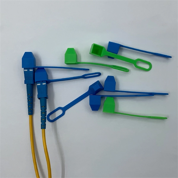
A simple rule is that each device needs two cores—one for sending and one for receiving data. Start by counting how many devices you're connecting. For example, if you have 10 devices, you'll need at least 20 cores. The total number of cores for a 1pc fiber patch cable is calculated as the number of branches multiplied by the number of cores per branch (if there are no branches, the number of branches = 1). For example, the total number of cores in an MTP®-8 trunk cable equals 4 (number of branches) x 8 (MTP-8. The number of optical cores in an optical fiber is the total number of equipment interfaces multiplied by 2, plus 10% to 20% of the spare quantity, and if the communication mode of the equipment has serial communication and equipment multiplexing, you can reduce the number of cores. The number of. One key factor is the number of cores, which impacts how much data you can transmit. This post will guide you through understanding fiber optic cores and selecting the perfect cable for your needs. Understanding Fiber Cores: Core: The central glass fiber that transmits light signals. For example, an MTP®-8 trunk cable with four branches and eight. Tip: Round counts to the connector pack before you buy. Tip: Keep one spare block for moves, adds, and changes. To calculate teh total number of fiber strands that will be.
[PDF]

A junction box contains four trade size 3 raceways: two on the left side, one on the right side, and one on the bottom. Once conductors have to turn, be pulled through, or be spliced inside an enclosure, the box dimensions start affecting installation time, conductor damage risk, and inspection results. A raceway design that looks fine in a panel schedule can still become a problem if the box is too short for an. Pull boxes, junction boxes, and conduit bodies must be sized to allow conductors 4 AWG and larger to be installed without damage to the conductor insulation. The NEC provides sizing requirements in 314. The distance between raceway entries enclosing the same conductor must be at least 6 times the trade. To size a junction box correctly, first decide whether NEC 314. Use box-fill rules for splices and devices, and pull-box rules for large conductors and raceways. The most common mistake is using the wrong. NEC 314. 28 specifies the minimum size requirements for pull and junction boxes in electrical installations. Proper sizing ensures conductors can be installed without damage and allows for proper bending space. How Does the Calculator Work? The calculator uses NEC 314. Minimum Length = 8 × Largest Conduit Size Minimum Dimension = 6 × Largest +.
[PDF]
The Aggregation Switch has a 160 Gb/s switching capacity with a 119. 04 Mpps forwarding rate, features steel construction with a fanless design, and can be rack mounted using the included kit. An Aggregation or "Top-of-Rack" switch is designed to connect everything in a rack at high speeds, then have an even bigger pipe out to the rest of the network. Power Consumption A 32-port, Layer 3 switch made for high-capacity 10G SFP+ and 25G SFP28 connections. The three layers of a traditional three-layer network design are the core layer, aggregation layer, and access layer. As the physical part of the aggregation layer, aggregation switches typically play a. IEEE 802. 3ad link aggregation enables you to group Ethernet interfaces to form a single link layer interface, also known as a link aggregation group (LAG) or bundle. The LAG balances. What is an Aggregate Switch? Understanding Centralized Network Management An aggregate switch is a high-capacity network switch that consolidates connections from multiple access switches, acting as a central point for managing network traffic and providing enhanced bandwidth capabilities. It is. Switch aggregation, also known as link aggregation or trunking, is a method used in computer networking to combine (aggregate) multiple network connections in parallel. This arrangement increases throughput beyond what a single relationship could sustain, offers redundancy in case one of the links.
[PDF]

Abstract:The design, installation, and protection of wire and cable systems in substations are covered in this guide, with the objective of minimizing cable failures and their consequences. In modern electrical systems, cable distribution boxes (also known as electrical distribution boxes or distribution boxes) play a crucial role as the key hub for managing, distributing, and protecting circuits. Whether it is residential buildings, commercial facilities or industrial sites, the. The power demanded in electricity systems also determines the cable cross-section and properties as well as the current to be transferred. In case of high power use, to meet the demand of currentAnd in order for the current to be carried at the demanded high powers to be met, the method of parallel. A distribution box is the heart of any electrical system. It takes the incoming power and safely distributes it to different circuits throughout your building. Whether in a home or an industrial facility, this box keeps your electrical setup organized, functional, and efficient. However, the key to. Distribution Board or DB is an electricity supply system or a common enclosure that distributes the electrical power feed into subcircuits. Armored Cable (Type AC). Armored cable is an assembly of insulated conductors, 14 AWG through 1 WG, wrapped with waxed paper. The conductors are contained within a fl exible spiral metal (steel or al minum) sheath that the edges.
[PDF]

Part two of this series provides details on how to build the beam splitter. It is made from regular float glass without any coating. Watch part 1 if you want. A beam splitter or beamsplitter is an optical device that splits a beam of light into a transmitted and a reflected beam. It is a crucial part of many optical experimental and measurement systems, such as interferometers, also finding widespread application in fibre optic telecommunications. a laser beam) into two (or sometimes more) beams, which may or may not have the same optical power (radiant flux). One beam is typically reflected while the other is transmitted. The ratio of reflected to transmitted light can vary based on the design of the beam splitter. Types of Beam Splitters: Cube Beam. The SPIE Digital Library offers a wide range of resources on beam splitters, focusing on their design, applications, and performance across various optical systems. The library includes research papers, conference proceedings, technical articles, and book chapters that cover both theoretical and. Beamsplitters are optical components used to split incident light at a designated ratio into two separate beams. Beamsplitters are often classified according to their construction: cube or plate.
[PDF]
