
A differential encoder is often used for bit synchronization. The polarity of the differentially encoded signal can be inverted without having any effect on the decoded signal waveform. A photoelectric signal, output by a photoelectric receiver, may detrimentally change after the photoelectric encoder is used for a period of time or when the environment changes; this will directly affect the accuracy of the encoder and lead to fatal errors in the encoder. To maintain its high. The grating eddy-current of DGECE consists of a circular array of trapezoidal reflection conductors and 16 trapezoidal coils with a special structure to form a differential relationship, which are respectively located on the code plate and the readout plate designed by a printed circuit board. 2 Example showing decoding is the same. This encoder signal error means your A, B, or R channels aren't correctly inverted. Learn how to test your encoder, cabling, and signal integrity. In high-performance control systems using the Siemens SINAMICS drive family, the encoder feedback is crucial. This also changes the direction of the rotation of the constellation changes. In the past I have been told channels. But I have also read that a spectral inversion is equivalent indicate this may be true.
[PDF]

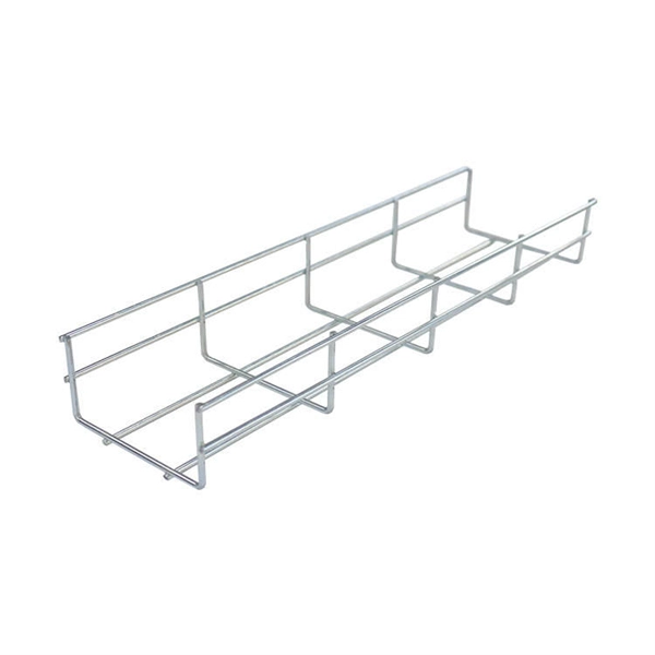
Cable tray support quantity can be calculated using a simple formula: Support Quantity = Total Length ÷ Support Spacing + 1 20 ÷ 2 + 1 = 11 supports In a typical project, a 20-meter cable tray with 2-meter spacing requires 11 supports. This article explains the principles, methods, and practical examples for calculating cable tray support quantity. Ensure NEC compliance, estimate wire length/weight, calculate deflection, and generate hardware BOMs for bends, tees, and reducers. Ideal for electrical contractors and engineers. The. This guide provides a comprehensive approach to calculating cable tray loads, considering various factors such as cable weight, tray weight, environmental influences, and safety factors. Classification of Loads Cable tray loads can be classified into the following categories: Dead Load (G): This. This page also guides to determine the appropriate distance between supports for the load, based on number of cables, cable tray size, and bracket type. Wire Mesh Cable Tray Fill Ratio = Cross section of cable / Cross section of tray According to NEC 392. 9 (B), when using ventilated tray with multi. The National Electrical Code (NEC) covers many aspects of cable tray supports and fittings. The National Electrical Code is a set of principles designed to promote public safety and welfare, as well as safeguard public health by regulating the design and operation of electrical facilities and.
[PDF]
As an important part of optical fiber communication, optical modules are optoelectronic devices that realize the functions of photoelectric conversion and electro-optical conversion in the process of optical signal transmission. A photoelectric conversion module includes a circuit board, a flexible substrate configured on the circuit board, with a concave structure having a first optical micro-reflection surface and a second optical micro-reflection surface formed opposite to the first optical micro-reflection surface, an. These two products are part of the LIGHTPASS ® Series active optical modules expected to be used for optical interconnection applications and IOWN* structures used for data centers and other uses. Demo kits for evaluating these products will be available from September 2023, and mass production is. The photoelectric conversion efficiency of optical modules is crucial, and it directly affects the quality and performance of optical communications. HISILICON has taken a variety of measures to improve photoelectric conversion efficiency. From the technical level, HISILICON makes improvements. The function of optical transceiver module is to perform photoelectric conversion, and its internal TOSA, ROSA and BOSA are the key components to realize the photoelectric conversion function. It is possible to calculate the power flowing into the active region as.
[PDF]

When comparing plate/mirror and cube beam splitters, the mirror splitters can tolerate more powerful beams of light, but the cubes have far better durability and are easier to handle. A beam splitter or beamsplitter is an optical device that splits a beam of light into a transmitted and a reflected beam. It is a crucial part of many optical experimental and measurement systems, such as interferometers, also finding widespread application in fibre optic telecommunications. Beamsplitters are often classified according to their construction: cube or plate. 📦 For purchasing, use the RP Photonics Buyer's Guide for beam splitters. It provides an expert-curated supplier directory, buyer-focused technical background information, and structured selection criteria to support professional procurement decisions. 2. Plate beamsplitters have a number of advantages over cube beamsplitters. The beam splitter splits and then recombines infrared radiation, while the detector picks up the resulting signal. It's sensitive to both intensity and frequency. Together, they decide just how accurately an instrument.
[PDF]
Photovoltaic (PV) modules are engineered for decades of reliable service, but they are not immune to failure. The primary culprits behind their degradation and eventual failure are environmental stress, manufacturing defects, material breakdown, and physical damage. Abstract:With the global increase in the deployment of photovoltaic (PV) modules in recent years, the need to explore and understand their reported failure mechanisms has become crucial. Some. This detailed analysis by Task 13, provides essential insights into the reliability and performance of cutting-edge photovoltaic technologies, focusing on the degradation and failure modes affecting new solar cells and modules, including perovskite-based technologies. Some degradations. The PV failure fact sheets (PVFS, Annex 1) summarise some of the most important aspects of single failures.
[PDF]
Photoelectron spectroscopy (PES) is an experimental technique that measures the relative energies of electrons in atoms and molecules. Scientists often use PES to study the elemental composition of mater.
[PDF]

