
The six-phase sequence current protection tester is an advanced device used to verify complex protection devices. Its core principle lies in the simultaneous output of six independent current and voltage signals to simulate various normal and fault conditions in a power system. It not only supports. In the complex world of power system protection, the Six Phase Relay Protection Test Set has emerged as an indispensable tool for engineers and technicians. These advanced devices play a critical role in verifying the reliability and accuracy of protective relays, ensuring the safe operation of. The CMC 356 is the universal solution for testing all generations and types of protection relays. Its powerful six current sources (three-phase mode: up to 64 A / 860 VA per channel) with a great dynamic range, make the unit capable of testing even high-burden electromechanical relays with very. JBC-806tester can simultaneously outputstandard six-phase current and six-phase voltage with 30A/phase current and 125V/phase voltage. With its six-phase output, this tester provides comprehensive testing capabilities, making it an essential instrument for ensuring the. nation in general. Not influenced by load, they contribute to protection speed and sensitivity. However, sequence components are present for a range of conditions, not only faults: open pole, load and line unba ance, breaker pole scatter, and current transformer ratio errors and saturation, to name.
[PDF]

The circuit diagram of the protective relay is made up of current transformer primary windings, current transformer secondary windings, relay operating coils, circuit breakers, and the tripping circuit. The relays are in round glass cases. The rectangular devices are test connection blocks, used for testing and isolation of instrument transformer circuits. In electrical engineering, a protective relay is a relay device designed to trip a circuit breaker when a fault is detected. : 4 The first. The working of a protective relay is based on continuous monitoring of electrical quantities such as current, voltage, frequency, and power. A typical protective relay circuit is shown below: Protective Relay Circuit Diagram The first part of the circuit consists of the primary winding of a CT. A relay is a four-terminal electrical switch, used to control any electrical circuit with an independent low-power signal and also to control various electrical circuits with a single signal. The terminals of the relay mainly include; common, coil, NO (normally open) & NC (normally closed). It functions as a watchdog by constantly surveying multiple system components including voltage, current, frequency, and phase angle. During a fault condition, there is a change. Protective relays and devices have been developed over 100 years ago to provide “lastline”of defense for the electrical systems.
[PDF]

This paper presents a set of newly developed modeling, simulation and testing tools aimed at better understanding the design concept and related applications for protective relaying and substation automation solutions for the smart grid. presentation of protection and control relaying. The report will identify methodology behind these practices, present issues raised by the integration of microprocessor relays and the internal logic and external communication configurations, ying. At Keentel Engineering, we specialize in modeling, simulating, and deploying advanced protective relays to ensure the robustness of medium-voltage (MV) and high-voltage (HV) networks. Our engineering services help utilities, OEMs, and renewable developers simulate real-world contingencies and. This Modern Power System Protective Relaying training course has been designed to provide a clear and perfect understanding of power system protection schemes and devices, including protection relays, fuses, circuit breakers, and other protective devices. In modern power systems, nowadays. To ensure that protective relays, circuit breakers, and other protection devices correctly and selectively isolate faults, minimizing damage to equipment and interruptions to customers while maintaining system stability. One-line diagrams and detailed network data (lines, transformers, buses).
[PDF]
The various protective functions available on a given relay are denoted by standard. For example, a relay including function 51 would be a timed overcurrent protective relay. An overcurrent relay is a type of protective relay which operates when the load current exceeds a pickup value. It is of two types: instantaneous over current (IOC) relay and definite time overcurrent (DTOC) relay.
[PDF]

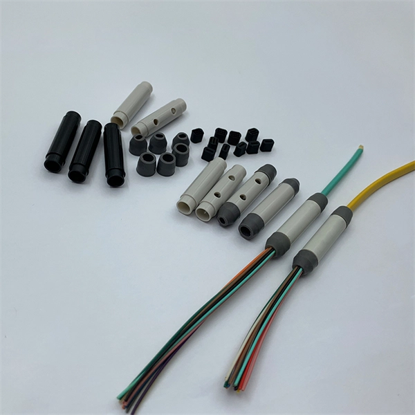
As a critical component in high-speed networks, fiber optic patch cords require micron-level precision. This guide unveils the complete production workflow compliant with **IEC 61754** and **Telcordia GR-326-CORE** standards, featuring proprietary quality control. If you've ever troubleshot a fiber optic network only to find that a microscopic dust particle caused the entire system failure, you understand why IPC-8497-1 exists. This standard represents the industry's collective wisdom on how to properly clean and assess contamination in optical assemblies. For harsh environments or other data center and IT networking applications where there is a greater risk of damage to your fiber optic network, armored fiber optic cables deliver the protection you require. Built with a steel-armored layer that provides extra crush and rodent resistance, these. Welcome to be our agent! Fiber optic patch cords, also known as fiber jumpers, are essential components in high-speed data transmission networks. Their performance directly impacts signal quality, insertion loss (IL), and return loss (RL). At ZION Communication, we design and manufacture a full range of fiber patch cords for: This guide will help you quickly understand the main types of. Ensuring the performance and reliability of fiber optic patch cords is fundamental to optical network integrity. 6-Step Manufacturing.
[PDF]

What is a Full Wave Rectification? Full wave rectifications are a specific type of rectification that transforms the entire AC signal cycle into a pulsing DC signal, one half at a time. Full-wave rectification converts alternating current to DC using numerous diodes. The full wave rectifier converts both halves of each waveform cycle into pulsating DC signal using four rectification diodes. In the previous power diodes tutorial we discussed ways of reducing the ripple or voltage variations on a direct DC voltage by connecting smoothing capacitors across the. Full Wave Rectifier Definition: A full wave rectifier is defined as a device that converts both halves of an AC waveform into a continuous DC signal. Circuit Diagram: The circuit diagrams for both centre-tapped and bridge rectifiers show how diodes are used to ensure the conversion of AC to DC. For the conversion of AC voltage into DC voltage it uses two different types of circuit configurations i. Center Tapped Full Wave Rectifier and Full Wave Bridge Rectifier. Output Voltage: Produces a pulsating DC output with twice the frequency of the. The process of converting the AC current into DC current is called rectification. Rectifiers are generally classified into two types: half wave.
[PDF]

At its core, an overcurrent relay operates on a very simple concept: detect excessive current, then trip fast and isolate the fault. When current surpasses the relay's pickup setting, an internal mechanism triggers the circuit breaker. IEEE/IAS/I&CPSD Protection & Coordination WG Chair Jacobs Canada, Calgary, AB rasheek. com IEEE Southern Alberta Section PES/IAS Joint Chapter Technical Seminar - November 2016 Protective Relays - Technical Seminar Nov 2016 - Copyright: IEEE 2 Abstract: Protective relays and devices. Relay protection against high current was the earliest relay protection mechanism to develop. From this basic method, the graded overcurrent relay protection system, a discriminative short circuit protection, has been formulated. Types of over current relay. It is really current monitoring relay. Overcurrent Relay Definition: An overcurrent relay is a protective device that operates solely based on current without the need for a voltage coil. These relays are known for their speedy operation during a fault and are hence used widely in high-voltage applications. Let's know in. The Art and Science of Protective Relaying, by C. Mason, John Wiley and Sons, 1956. Evaluation of Distribution System Relaying Methods, by A. McConnell, Presented at the Pennsylvania Elec-tric Association, May 16-17, 1957.
[PDF]

Traditional electromechanical relays rely on fixed settings that cannot adapt to variable grid conditions. This often results in miscoordination, delayed fault clearing, or unnecessary tripping, compromising reliability. able sources such as wind and solar. These clean energy sources, connected through inverters and flexible transmission systems, are transforming traditional grids based on synchronous generators into more flexibl cant challenges to system stability. Nowhere is that clearer than in the challenge to. Relay protection systems are essential in maintaining the safety and reliability of modern electrical grids. As technology advances and grids become smarter, the tools used to test and maintain these systems, such as the relay test set, are evolving to meet new challenges. This article explores the. By taking a series of countermeasures, the paper explored the influence of new energy connection on traditional relay protection systems in response to the occurrence of the above phenomenon. These countermeasures include protection logic and settings optimization, fast fault detection technology. Abstract—This paper discusses the impact of inverter-based resources (IBRs) in traditional digital protection relays applied in the interconnection transmission line between the IBR and bulk power system. This paper explores the development of relay protection technology in smart grids, analyzing.
[PDF]

This video provides a detailed walkthrough of designing and simulating an automatic light control system using Light-Dependent Resistor (LDR) and Triac in Proteus Software. Last updated on 13 August 2025 by Admin-Lavi Leave a Comment This article talks about Light Controlled Switch Circuit using IC LM311 and LDR. It simple and very useful and it feel light change near it. We find this circuit in many place like automatic light, street lamp and security system. Main. ABB's Control Room offering includes a comprehensive range of solutions designed to optimize the operator workspace for critical 24/7 processes across various industries. The project demonstrates how to create a smart lighting system that turns on/off automatically based. more This video. The Intro Screen changes as you play with it. It has a Play Area and a Control Area. A Construction Area creates a building space for components added from a Circuit Component Toolbox. Build and navigate your circuits there. If Voltmeters and Ammeters are out of the toolbox, you can take. Common sense schematics let you name a node "+5V" and know that the simulator will do the right thing automatically, keeping your schematics compact and elegant. This circuit activates or deactivates connected loads, such as LEDs or light bulbs, based on ambient light levels.
[PDF]

Protective relays are special electrical devices used to detect faults in power systems and quickly disconnect faulty parts to prevent damage. These relays sense abnormal conditions like overcurrent, under-voltage, or short circuits and send a signal to circuit breakers to open the. Electromechanical protective relays at a hydroelectric generating plant. The relays are in round glass cases. The rectangular devices are test connection blocks, used for testing and isolation of instrument transformer circuits. In electrical engineering, a protective relay is a relay device. Protective Relay Definition: A protective relay is an automatic device that senses abnormal conditions in electrical circuits and triggers actions to isolate faults. Types of Protective Relays: Protective relays are categorized by their mechanism (electromagnetic, static, mechanical) and function. Combines protection, sensors, control power, and circuit breaker in a single package Typically added to a breaker close circuit to prevent accidental reclosure after a trip. Three fundamental components required for each circuit breaker. It initiates the operation of circuit breakers to isolate the affected section.
[PDF]

The National Electrical Code (NEC) does not specify the maximum distance for a ground rod from a panel. However, the ground rod should be placed as close as possible to the panel to ensure an effective ground connection. Electrical clearances set the minimum safe distances for panels, overhead lines, pools, and buried wiring — and ignoring them has real consequences. (If these areas are accessible to other than pedestrian traffic, then one of the other conditions applies). Above finished grade or sidewalks, or from any platform or projection from which they. Learn key electrical code requirements for junction boxes, including sizing, grounding, materials, and clearance to ensure safety and efficiency. Whether it's a. The National Electrical Code (NEC) provides comprehensive safety standards for electrical installations, including requirements for electrical panels (main service panels and subpanels or breaker box). NEC Article 408 covers switchboards, switchgear, and Panelboards installation and applications. Following the manufacturer's installation instructions for the ground rod and.
[PDF]
Choose the right box based on environment (indoor/outdoor), load capacity, and durability. Check for proper IP/NEMA ratings and material quality. Ensure safe placement: install in dry, accessible areas with good ventilation and at appropriate height (typically ~1. Practice good wiring: secure. An electrical distribution box, also known as a power distribution box, panelboard, or consumer unit, is the core of an electrical system. It has three categories: residential, commercial and industrial electrical distribution boxes, all of which play important roles in their respective electrical. When you install a distribution box, you need a variety of tools to get the job done safely and efficiently. To install distribution box systems, you'll use hand tools such as screwdrivers and pliers. Wire strippers are essential when you install distribution box wiring. A measuring tape and. This guide offers an in-depth exploration of installing electrical distribution boards, highlighting essential steps, safety measures, and the integration of business intelligence tools to optimize your work. Just like travelers need clear pathways and safety protocols, your electrical circuits need proper management to prevent chaos. The National Electrical Code (NEC) requirements might seem like bureaucratic.
[PDF]

This section applies to grounding of transmission and distribution lines and equipment for the purpose of protecting employees. Note to paragraph (a): This section covers. Correct grounding of services depends upon understanding the definition and role of the grounded conductor. The neutral conductor is typically the grounded conductor connected to the system's neutral point, carrying current under normal operation. Grounding electrode conductors must be connected at. Learn the grounding and bonding rules when powering two or more buildings or structures in the same area with a single service. To catch up on Lorenzo Mari's series on National Electrical Code 2023 Basics: Grounding and Bonding, follow these links: NEC's Section 250. Bonding is connecting things together with a conductive path to establish electrical continuity. Both are foundational safety concepts in the NEC, and. NFPA 70: National Electrical Code Article 250 covers the minimum requirements for grounding and bonding and, although the NEC lists requirements to abide by, it should not be taken as a design manual. Some terms and requirements discussed may be true for the European standards, however, the intent.
[PDF]
