This guide provides CISOs and IT leaders with an in-depth look at network security architectures. Perimeter security is the first line of defense, protecting the network from external threats. It includes firewalls, intrusion prevention systems (IPS), and other security devices that control network traffic at the network's boundary. When effectively designed, network security reduces threats like unauthorized access and malware from impacting your network or. Network security architecture is a strategy that provides formal processes to design robust and secure networks. Effective implementation improves data throughput, system reliability, and overall security for any organization. It explains the key concepts in plain language, dives into the core components, shares a framework for. Microsoft Defender for Cloud provides cloud security posture management (CSPM) and cloud workload protection (CWP). It assesses your resources for security compliance, provides a secure score to track your posture, and offers threat protection across Azure, on-premises, and multicloud workloads. It encompasses hardware, software, policies, and procedures.
[PDF]

The LAN-WDM grid consists of four primary wavelengths in the 1310 nm window: These wavelengths were selected to minimize dispersion and allow cost-effective optical component design. LAN-WDM, short for Local Area Network Wavelength Division Multiplexing, is a specialized optical transmission technique that allows multiple high-speed optical signals to be transmitted over a single fiber using closely spaced wavelengths. Originally developed to support high-speed Ethernet. As an essential component of optical fiber communication, optical modules are optoelectronic devices that facilitate the conversion between optical and electrical signals during the transmission process. Operating at the physical layer of the OSI model, optical modules are core devices in optical. In the era of 5G, AI, and high-speed data centers, optical modules serve as the core bridge for converting electrical signals to optical signals (and vice versa), enabling fast, reliable data transmission across networks. It works by dividing light into multiple wavelengths, allowing you to send more data simultaneously over a. With the increasing demand for data centers and high-speed communications, LAN-WDM (LWDM) technology, as an emerging wavelength division multiplexing solution, is gradually becoming the focus of industry attention. This guide delves into the principles, types, applications, and future trends of WDM. Tailored for professionals sourcing solutions from CommMesh, it.
[PDF]
This ultimate guide explains what a distribution box does, its internal components, common types, real-world applications, and how to select the right DB Box for your project. A distribution boxes is an essential device that manages the safe and efficient flow of electrical power throughout different areas of a building or facility. It is commonly used in homes, offices, and industrial settings to control and protect electrical circuits. Inside, you'll find parts like circuit breakers and fuses that protect the system from problems like overloads and short circuits. By knowing their great. A well-chosen and properly installed distribution box can prevent electrical hazards, reduce downtime, and ensure your electrical system operates smoothly for years to come. Let's explore how these critical components work and why they deserve your attention. A distribution box, also known as a. The internal structure of the distribution box is designed to safely distribute power from the main power source to multiple branch circuits. We also highlight how reliable manufacturers like NUOMAK support stable, compliant, and cost-effective power distribution.
[PDF]

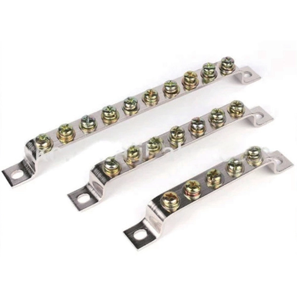
When building the wall, the reserved hole should be about 20 mm larger than the length and width of the distribution box, and the reserved depth is the thickness of the distribution box plus the plastering thickness of the inner wall of the hole. A technology for distribution boxes and interior walls, applied in manufacturing tools, ceramic molding machines, molds, etc., can solve problems such as affecting the construction process and construction period, and one-time consumption of thermal insulation boards, so as to reduce labor and. Legal status (The legal status is an assumption and is not a legal conclusion. Google has not performed a legal analysis and makes no representation as to the accuracy of the status listed. ) Current Assignee (The listed assignees may be inaccurate. Incoming Porcelain Fuse units as per IS: 2086/1993 with latest Amendment/ Revision if any on the ization of. How to distribute the distribution box reasonably? 1. 1 Facilities serving other customers in the Central Business District (CBD) in downtown areas of Dallas and Fort Worth are operated per Tariff for Retail Delivery Service. Tariff for Retail Delivery Service 6. 1 A unique type of. To join a Viva Engage community and take part in the latest discussions, fill out the Request access to Finance and Operations Viva Engage Community form and choose the community you want to join. The Put to wall - put to store functionality lets you handle scenarios where you must consolidate a.
[PDF]

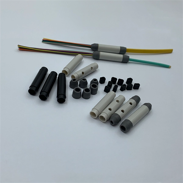
BiDi transceiver, or Bidirectional or simplex optical transceiver, is an optical module that uses Wavelength Division Multiplexing (WDM) technology to transmit and receive data over a single-strand fiber simultaneously. By replacing one of the light sources with LEDs, cost reduction and higher reliability can be achieved. Since the relationship is as shown on the right, simply replacing the VCSEL with an LED has extremely poor coupling efficiency. It achieves simultaneous bi-directional communication by using different. Single-mode fiber is designed to carry a single light mode, allowing signals to travel further with minimal attenuation (signal loss). Multimode fiber transmits multiple light modes, suitable for shorter distances due to dispersion and attenuation. In typical fiber-optic networks, two fiber strands. The WDM system supports two transmission modes: single-fiber unidirectional and single-fiber bidirectional. Simple design and low requirements. This physical-layer design instantly doubles existing cable plant capacity without requiring expensive new.
[PDF]

THIS REPORT WAS PREPARED BY THE ORGANIZATION(S) NAMED BELOW AS AN ACCOUNT OF WORK SPONSORED OR COSPONSORED BY THE ELECTRIC POWER RESEARCH INSTITUTE, INC. NEITHER EPRI, ANY MEMBER OF EPRI, ANY COSPONSOR, THE ORGANIZATION(S) NAMED BELOW, NOR ANY PERSON ACTING ON BEHALF OF ANY OF. Vogtle Electric Generating Plant (VEGP) Units 3 and 4 Updated Final Safety Analysis Report, Revision 3, Section 3, Appendix 3F Cable Trays and Cable Tray Supports. This appendix provides the design criteria for seismic Category I cable trays and their supports. Seismic Category II cable trays and. The Pacific Earthquake Engineering Research (PEER) Centre has been developing a performance-based earthquake engineering (PBEE) methodology, which is based on explicit determination of performance, e. These rules have to be respected scrupulously by the engineering. Cable trays play a vital role in supporting electrical cables and wires in commercial, industrial, and utility installations. For proper installation, design, and maintenance, adherence to international standards is essential. One of the most recognized frameworks globally is the IEC standard for. CTI has committed most of its energies towards support services. The Cable Tray Institute is now making available our complete library of technical articles which have appeared in the Cablegram. For further assistance, contact David Richmond (NEMA Senior Program Manager) at David.
[PDF]

Optical fiber cables consist of several key components, including the core, cladding, coating, strengthening fibers, and outer jacket, each essential for effective data transmission. Communication optical cable is a common wiring product. You should choose according to the nature of the specific project. Communication cable structure cable core Cable core: It is located in the center of the optical cable and. A TOSLINK optical fiber cable with a clear jacket. These cables are used mainly for digital audio connections between devices. A fiber-optic cable, also known as an optical-fiber cable, is an assembly similar to an electrical cable but containing one or more optical fibers that are used to carry. An optical fiber cable is a complex structure designed to protect fragile glass fibers that transmit digital data using light signals. This advanced cabling solution allows fast, secure data transfer and telecom over long distances. Understanding the components within a fiber optic cable enables. This series of courses are based on the Navy Electricity and Electronics Training Series (NEETS) section on Fiber Optic cable systems. The NEETS series is produced by the Naval Education and. This Lesson Learned is based on Maintainability Technique number OPS-08 from NASA Technical Memorandum 4628, Recommended Techniques for Effective Maintainability. It then discusses the history of optical fibers and their structure.
[PDF]

An explosion-proof distribution box is a special electrical equipment designed for flammable and explosive environments. Its shell is made of high-strength materials (such as aluminum alloy or stainless steel), and its internal structure is strictly sealed. Customers often inquire about the internal wiring of explosion-proof distribution boxes. 5 to 10 kilowatts, suitable for using 220-volt fans and. Specification code(I,II,IIB. Flameproof enclosure (Ex d IIB+H2), which can be used as feed distribution equipment in control and distribution system (such as distribution box, switch box of main circuit, control box, terminal box or motor starting box etc. ) ·Enclosure: stainless steel. They prevent sparks, arcs, or high temperatures generated by internal electrical components from coming into contact with explosive gases or dust in the surrounding atmosphere. Substructure (use SSS=) and similarity (use ~) searches are limited to one per search at the top-level AND condition. Exact searches can be used multiple times throughout the search query. Searching by SMILES or InChi key requires no special syntax. To search by SMARTS, use SMARTS=. To search for. The explosion-proof distribution box is the "invisible guard" that ensures the safe operation of the power system in these special environments. The outer surface of the Distribution Box shell is coated with silver-gray powder paint.
[PDF]

Optical Transmitter: Converts electrical signals into optical signals for transmission. Optical modules are devices used to connect network devices, transmit and receive data between network devices, and can be used to convert optical and electrical signals. The optical module is a very important component in an optical communication system. This article will introduce you to the. d launches the optical signals into an optical fiber. A fiber optic transmitter consists of an interface c rcuit, a source drive to make it compatible with the source drive circuit. The source drive circuit intensity modulates the opt cal source by varying the current through the source. But what exactly is happening inside this powerful little component?In this article, we'll pull back the curtain and explore the inner. Optical transmitters are a crucial component in modern telecommunications, enabling the transmission of data as light signals through optical fibers. In this comprehensive guide, we will explore the definition, importance, and evolution of optical transmitters, as well as their types, applications. Role: Convert optical signals back into electrical signals and reconstruct the transmitted information., PIN diode or avalanche photodiode). Demodulation circuitry to extract the transmitted data. These requirements define digital transceivers as well as analog receivers and transmitters.
[PDF]

An optical module is mainly composed of optoelectronic devices (including the optical transmitter and optical receiver), functional circuitry, and optical interfaces. Its fundamental role is to bridge the gap between electrical equipment and optical fibers. Optical modules are key components in fiber optic communication systems, responsible for electro-optical conversion, meaning the conversion of electrical signals to optical signals or vice versa. The internal structure of an optical module is complex but can be divided into several main parts. As an essential component of optical fiber communication, optical modules are optoelectronic devices that facilitate the conversion between optical and electrical signals during the transmission process. Operating at the physical layer of the OSI model, optical modules are core devices in optical. This comprehensive guide breaks down the internal structure, core components (TOSA, ROSA, lasers), and operational mechanisms of SFP optical modules, enriched with technical insights and real-world applications. It is available in TO-CAN, Gold-BOX, COC (chip on chip), COB (chip on board), and other packaging forms. This article will introduce you to the.
[PDF]
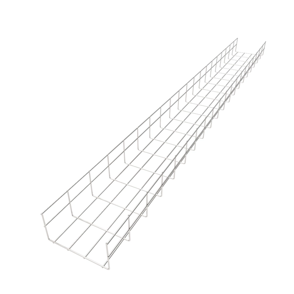
Made from recycled high strength steel or aluminum – a green solution, our trays are reusable and reclaimable. Do not require field fabrication – hand-bendable trays easily work around obstacles, or.
[PDF]

Cable tray support quantity can be calculated using a simple formula: Support Quantity = Total Length ÷ Support Spacing + 1 20 ÷ 2 + 1 = 11 supports In a typical project, a 20-meter cable tray with 2-meter spacing requires 11 supports. This article explains the principles, methods, and practical examples for calculating cable tray support quantity. Ensure NEC compliance, estimate wire length/weight, calculate deflection, and generate hardware BOMs for bends, tees, and reducers. Ideal for electrical contractors and engineers. The. This guide provides a comprehensive approach to calculating cable tray loads, considering various factors such as cable weight, tray weight, environmental influences, and safety factors. Classification of Loads Cable tray loads can be classified into the following categories: Dead Load (G): This. This page also guides to determine the appropriate distance between supports for the load, based on number of cables, cable tray size, and bracket type. Wire Mesh Cable Tray Fill Ratio = Cross section of cable / Cross section of tray According to NEC 392. 9 (B), when using ventilated tray with multi. The National Electrical Code (NEC) covers many aspects of cable tray supports and fittings. The National Electrical Code is a set of principles designed to promote public safety and welfare, as well as safeguard public health by regulating the design and operation of electrical facilities and.
[PDF]
A fiber-optic cable, also known as an optical-fiber cable, is an assembly similar to an but containing one or more that are used to carry light. The optical fiber elements are typically individually coated with plastic layers and contained in a protective tube suitable for the environment where the cable is used. Different types of cable are used for in different applications, for exa.
[PDF]