
Buy Panduit LabelCore Fiber Optic Cable Identification System Self-Laminating Laser/Ink Jet Labels at SHI. See detailed specifications and benefit from expert support. Shop IT hardware and software products with SHI now!. Indoor & outdoor fiber cable high visibility markers, id labels, printers, warning signs & posts, cable id sleeves and more for fiber optic applications. Check each product page for other buying options. Need help? Explore write-on fiber optic cable tags with self-laminating protection. Keep your cables organized and clearly labeled with writable identification solutions. The Multilink cable markers utilize a simple and quick installation that allows the installer to simply wrap the marker around the selected cable without the need for special tools or adhesives. The UV stabilized body will not degrade in outside applications and a variety of colors allows easy. According to research conducted by industry experts that shows network failures cost businesses the equivalent of five thousand dollars per minute. If technicians aren't able to quickly recognize the correct cable, these minutes can add up quickly. The TIA/EIA-606-A standard has created a unified system that specifies a "common" method of labeling the complete telecommunication infrastructure. PANDUIT Labeling Software packages include all label formats for quick and.
[PDF]

Connecting a fiber patch cord involves carefully inserting it into the appropriate adapter after ensuring the connectors are clean. The process may differ slightly depending on the type of connector. The core process involves two main stages: preparation and insertion. Planning helps you pick the right cord for your network. Be gentle when you handle the cord. Fibre patch cords last longer and are tougher than copper cables. They also protect better from interference. Look at the table below to compare:. Connecting a fiber optic patch panel may seem daunting at first, but if you follow the right steps, it's actually quite simple – and can even be done in just a few minutes. Preparation: Before. Fiber Optic Transceivers: For converting signals between optical and electrical form. Cleaver: For precisely cutting the fibers. Safety Equipment: Gloves. In today's high-performance networks, fiber optic patch cables are the lifelines that ensure smooth data flow across switches, servers, and routers. Even the most advanced optical transceivers can only perform at their peak when paired with properly installed, clean, and precisely managed fiber. Correct patch-cord installation is essential for maintaining low insertion loss, stable return loss, and long-term reliability in both indoor and outdoor fiber networks. Proper handling, routing, cleaning, bend-radius management, and connector alignment ensure that the optical link meets design.
[PDF]

Read on to learn how a systematic approach can streamline the process, mitigate risks, and elevate overall performance in telecommunications carriers. Fiber optic cables form the backbone of modern data transmission in telecommunications. Cable identification stands as a critical practice in fiber optic networks. Misidentification can cause downtime, disrupt essential services, and create safety hazards in data centers. Industry standards like TIA-606-B guide professionals to use color codes, print legends, connector types, and. Fiber Optic Cable Tags are the perfect choice for marking your ground level and underground cables. Custom Fiber Optic Tags available upon request. Sold in package of 50 (nylon ties sold separately). Online shipping rates and pricing may differ. Indoor & outdoor fiber cable high visibility markers, id labels, printers, warning signs & posts, cable id sleeves and more for fiber optic applications. Need help? Explore write-on fiber optic cable tags with self-laminating protection. Keep your cables organized and clearly labeled with writable identification solutions. Cable Tags (Cable ID Tags, Fiber ID Tags) simplify wire and cable identification! Cable Tags (Cable ID Tags, Fiber ID Tags) simplify wire and cable identification! Fiber Tag Generic (No Company name) 4 Inches long fits 1/2" to 1" line. They are responsible for carrying vast amounts of.
[PDF]

This Quick Reference Guide is intended to provide highlights of OPGW installation instructions needed in the field. Please review the document (WI-0298 Rev 1) before proceeding with. Describe the system used for installation and delivery of OPGW fibre optic cables. - SCOPE This document covers all the activities usually performed by PRYSMIAN for on-site installation of OPGW fibre optic cables, including transport, installation, accessory assembly, verification of optical. This manual is formulated in accordance with IEEE 1138 - 2008 and IEEE 524 - 1992, etc. OPGW has dual functions of aerial ground wire and fiber communication. To. The OPGW cable installation process 2 involves careful preparation, precise laying and stringing, installation of necessary hardware, and thorough testing. I have seen that following these steps makes the installation work well and ensures high performance and reliability. I once worked on a. Discover the perfect fiber training course for your career path. This fiber optic training course is designed for those who specify, design, install, construct or maintain aerial Optical Power Ground wire systems in investor-owned, Electric Power Utilities, REAs, Co-operatives, and municipal power. Optical Ground Wire (OPGW) is a crucial component for reliable communication in power transmission systems. OPGW fiber optic cable is a unique type of cable that.
[PDF]

In this comprehensive guide, we'll walk through the best practices for installing various types of fiber optic cable, from patch cords to distribution fiber, and provide practical tips to ensure a successful installation. This article will guide you through the necessary tools, materials, and methods on how to connect fiber optic cables effectively, ensuring you achieve optimal performance from your fiber optic network. Have a network installation project? Fiber Optic Cables: The primary medium for your connections. A shaky connection means weaker signals, dropped streaming, or slow uploads. Get the hookup right, and you'll enjoy streaming, gaming, and video calls without interruptions. Fiber optic cables need careful handling. Why Use Fiber Optic Internet? Before diving into the setup, let's quickly recap why fiber optics are worth the effort: Lightning-fast speeds (up to 1 Gbps or higher). The number one cause of signal loss in optical fiber installations is dirt on. Setting up a fiber internet connection requires understanding key hardware components and following a specific connection sequence to establish your home network.
[PDF]

In this video, we'll walk you through the process of wiring a home distribution box with a detailed connection diagram. Whether you're an electrician or a DIY enthusiast, this guide will help you understand the basics of home electrical distribution. more Welcome to our. Material preparation: Prepare the required circuit breakers, wires, wiring ties and other materials, and ensure that they meet the design drawings and installation requirements. Location determination: Determine the installation position of the circuit breaker according to the position of the. An electrical panel box, also known as a breaker box or a distribution board, is a crucial component of any electrical system. It serves as a central hub for distributing electricity throughout a building, ensuring that power is delivered safely and efficiently to all the required locations. What is Distribution Board? Distribution board. A distribution board (also known as a service panel or breaker box) is a centralized collection of circuit breakers, fuses, and/or relays used to control and protect the wiring in a home. The diagram of the distribution board's wiring shows exactly how each circuit is wired and connected.
[PDF]

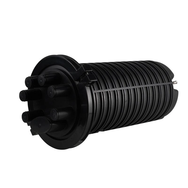
In this guide, you will find a chronological description of the fusion splicing process, the principal technical standards, and answers to the real-life questions network engineers and procurement teams may have. In this guide, we cover the basics of fiber optic splicing, how to perform splicing using two different methods, and finally some best practices to perform good fiber splicing. What is Fiber Optic Splicing and Why is it Needed? – #1. Use and Maintain Your. This Geoschematics drawing remains easy to read despite containing more than 2000 fibers and 500 splices. Splice Diagrams or Matrices capture an electric or optical network inside a location – documenting cables, ported equipment, and connections. Splices are fiber-to-fiber, port-to-fiber and. This guide will walk you through the complete process of fiber optic splicing—covering each step in detail so you can deliver a clean, professional splice every time. Before jumping into the physical steps, it's important to understand the two primary methods of fiber splicing: fusion splicing and. Page 1 The FOSC 450 fiber optic splice closures use compressed-gel cable seals to environmentally seal fiber cable splice points. FOSC 450-ab-c-dd-e-fgh The maximum single splice capacity of the FOSC 450 B6 closure is a = Closure size 144 with 24 splices stored on six trays. Therefore, we will also touch on cost factors, risk management, and best practices in.
[PDF]

The process involves a combination of national infrastructure, local engineering, and property-level setup. In this guide, we'll break down the fiber installation process from start to finish and explain key components such as fiber cabinets, flower pods, ducting, and ONT. Our fiber optic installation process covers everything from planning and preparation to termination and testing. But how does it work? Keep reading to find out. What Is Fiber Optic. This fiber optic installation method statement covers the termination of fiber optic cables with patch panel, network distribution cabinet NDC and door junction box but can be applicable for any kind of network installations. Roles and Responsibilities: The electrical manager shall be responsible. Setting up a fiber optic network requires careful planning and execution. This guide provides a step-by-step overview of the installation process, ensuring a smooth transition from traditional cabling systems. Introduction Installing a fiber optic network can seem daunting, but with the right. This beginner-friendly guide will walk you through the step-by-step process of fiber optic cable installation for each method, highlighting best practices, tools, and considerations. Unlike traditional copper wiring, fiber optics installation provides superior bandwidth, faster speeds, and resistance to electromagnetic interference.
[PDF]

Provides technical requirements concerning the construction, testing, and performance of metal cable tray systems. It is the first joint effort of NEMA and CSA International to put in one place standards for metal trays per both NEMA and CSA methods. Addresses shipping. Cable trays play a vital role in supporting electrical cables and wires in commercial, industrial, and utility installations. For proper installation, design, and maintenance, adherence to international standards is essential. One of the most recognized frameworks globally is the IEC standard for. association representing the major electrical equipment manufac-turers in the U. The Cable Tray ng standards, performance standards, test standards and application in this document have been tested extens ompetent professional en completely installed, without damage either to conductors or. CABLE TRAYS THE GLOBAL SPECIALISTIN ELECTRICAL AND DIGITAL BUILDING INFRASTRUCTURES TECHNICAL GUIDE Not all cable trays are equivalent. The mechanical and electrical characteristics, tests, certifications, overall quality management, recommendations mentioned in this technical guide only apply to. Not all cable trays are equivalent. For those of you that have experience working with cable tray systems, you have probably noticed the high-level of influence NEMA has in guiding cable tray management projects.
[PDF]
Optical data couplers are essential components in modern fiber optic networks. They enable the connection and distribution of light signals between fibers, facilitating high-speed data transmission over long distances. As digital communication demands grow, these devices become increasingly vital. Explore the role, types, and applications of fiber optic couplers in telecommunications and data networks in our in-depth article. They serve an essential role in managing the flow of light. A coupler is an optical device that combines or splits optical signals. Couplers can be used to split an optical signal into multiple signals, combine multiple signals into a. The same kind of device is useful in fiber interferometers, also for combining two inputs. (Note that polarization issues might occur. Unlike active devices like switches or transceivers, couplers require no electrical power to function.
[PDF]

Complete pv combiner box wiring diagram guide covering string connections, grounding methods, bonding requirements, and NEC-compliant installation procedures for solar systems. Most wiring diagrams supplied with commercial combiner boxes are simple, easy-to-understand. A clear wiring diagram helps installers understand the flow of current from each string to the main DC bus, making the system safer and easier to maintain. For systems with three or more DC strings, using a solar combiner box is recommended according to international PV safety standards such as IEC. This wiring diagram will guide you in understanding how to properly wire a PV combiner box. One of the key elements of a PV combiner box is the array of fuses or circuit breakers. These safety devices protect the solar panels from overcurrent and short circuits. Understanding proper wiring topology, conductor sizing methodology, and grounding. ing connections,fusing,and grounding. Following the diagram will help ensure the safety,efficiency,and long-term perform nce of your solar panel installat el off the outer shea h of the cable. Check if t is level. Check vertica deviation. Bandage exposed wire. Mea ure. This piece will address the components required for a DC PV combiner box, how to read its wiring diagram and provide a step-by-step tutorial on how to wire it safely and efficiently.
[PDF]
Pricing (EUR) Filter the results in the table by unit price based on your quantity. Bus Bar Connectors are available at Mouser Electronics. Mouser offers inventory, pricing, & datasheets for Bus Bar Connectors. Flex-Cable is a leading provider of bus bar solutions for all types of battery connections. We can design and create bus bars using a variety of materials to meet all customer specifications. Let us solve your battery and capacitor conductor routing and space problems! Flex-Cable bus bars provide:. From copper busbar and aluminum busbar options to insulated busbar and busbar trunking systems, our Busbar Products Pricing Guide helps you balance quality, durability, and budget to make the right choice. The European busbar market has witnessed significant growth and transformation over the years, driven by advancements in electrical infrastructure, increasing energy demands, and stringent environmental regulations. At EMDEP we have developed a busbar tester which is a precisely solution to perform High Voltage test for this type of product. A universal concept with interchangeable. Navigating Europe's complex cable manufacturing landscape requires precision. This definitive guide cuts through the concentrated USD 49. 40 billion market (2024 valuation), empowering procurement professionals and infrastructure developers to strategically source. We provide data-driven insights, a.
[PDF]

Fiber loopback offers numerous advantages in testing optical networks. One of its primary benefits is its ability to provide an end-to-end testing scenario, simulating real traffic conditions and allowing comprehensive assessments of network performance. Additionally, fiber loopback devices are. Given that the signal does not leave the device, a failure revealed during fiber loopback testing is always an indicator of an error with the transceiver and/or internal configuration and not with the fiber-optic connection. Fiber loopback finds extensive applications in various phases of network. Therefore, the fiber optic loopback streamlines the troubleshooting workflow, significantly reduces network downtime, and ultimately lowers operational costs. The market offers a diverse range of Fiber Optic Loopback devices, each designed to meet specific testing requirements related to different. Fiber loopback cables are essential for networking testing, and troubleshooting to validate the performance and integrity of optical links. Whether used in pre-deployment testing or ongoing diagnostics, fiber loopback cables are important tools for maintaining optimal network operations and. 4. 3 Advantages of Loopback Testing No live network required: Ideal for lab and deployment verification. Fast diagnosis: Can instantly confirm whether a device port is operational. We hope you find this guide helpful. What are loopback cables? What are loopback cables? A loopback.
[PDF]
