THIS REPORT WAS PREPARED BY THE ORGANIZATION(S) NAMED BELOW AS AN ACCOUNT OF WORK SPONSORED OR COSPONSORED BY THE ELECTRIC POWER RESEARCH INSTITUTE, INC. NEITHER EPRI, ANY MEMBER OF EPRI, ANY COSPONSOR, THE ORGANIZATION(S) NAMED BELOW, NOR ANY PERSON ACTING ON BEHALF OF ANY OF. Vogtle Electric Generating Plant (VEGP) Units 3 and 4 Updated Final Safety Analysis Report, Revision 3, Section 3, Appendix 3F Cable Trays and Cable Tray Supports. This appendix provides the design criteria for seismic Category I cable trays and their supports. Seismic Category II cable trays and. The Pacific Earthquake Engineering Research (PEER) Centre has been developing a performance-based earthquake engineering (PBEE) methodology, which is based on explicit determination of performance, e. These rules have to be respected scrupulously by the engineering. Cable trays play a vital role in supporting electrical cables and wires in commercial, industrial, and utility installations. For proper installation, design, and maintenance, adherence to international standards is essential. One of the most recognized frameworks globally is the IEC standard for. CTI has committed most of its energies towards support services. The Cable Tray Institute is now making available our complete library of technical articles which have appeared in the Cablegram. For further assistance, contact David Richmond (NEMA Senior Program Manager) at David.
[PDF]

BiDi transceiver, or Bidirectional or simplex optical transceiver, is an optical module that uses Wavelength Division Multiplexing (WDM) technology to transmit and receive data over a single-strand fiber simultaneously. By replacing one of the light sources with LEDs, cost reduction and higher reliability can be achieved. Since the relationship is as shown on the right, simply replacing the VCSEL with an LED has extremely poor coupling efficiency. It achieves simultaneous bi-directional communication by using different. Single-mode fiber is designed to carry a single light mode, allowing signals to travel further with minimal attenuation (signal loss). Multimode fiber transmits multiple light modes, suitable for shorter distances due to dispersion and attenuation. In typical fiber-optic networks, two fiber strands. The WDM system supports two transmission modes: single-fiber unidirectional and single-fiber bidirectional. Simple design and low requirements. This physical-layer design instantly doubles existing cable plant capacity without requiring expensive new.
[PDF]

When building the wall, the reserved hole should be about 20 mm larger than the length and width of the distribution box, and the reserved depth is the thickness of the distribution box plus the plastering thickness of the inner wall of the hole. A technology for distribution boxes and interior walls, applied in manufacturing tools, ceramic molding machines, molds, etc., can solve problems such as affecting the construction process and construction period, and one-time consumption of thermal insulation boards, so as to reduce labor and. Legal status (The legal status is an assumption and is not a legal conclusion. Google has not performed a legal analysis and makes no representation as to the accuracy of the status listed. ) Current Assignee (The listed assignees may be inaccurate. Incoming Porcelain Fuse units as per IS: 2086/1993 with latest Amendment/ Revision if any on the ization of. How to distribute the distribution box reasonably? 1. 1 Facilities serving other customers in the Central Business District (CBD) in downtown areas of Dallas and Fort Worth are operated per Tariff for Retail Delivery Service. Tariff for Retail Delivery Service 6. 1 A unique type of. To join a Viva Engage community and take part in the latest discussions, fill out the Request access to Finance and Operations Viva Engage Community form and choose the community you want to join. The Put to wall - put to store functionality lets you handle scenarios where you must consolidate a.
[PDF]
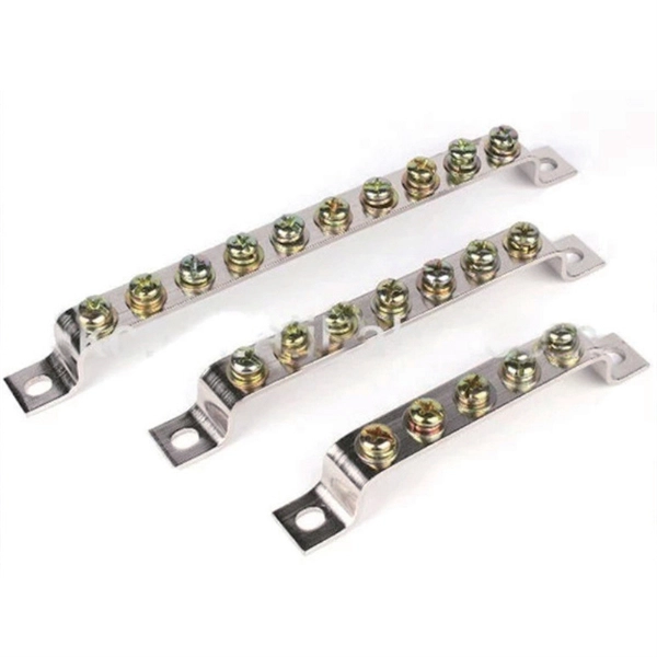
This ultimate guide explains what a distribution box does, its internal components, common types, real-world applications, and how to select the right DB Box for your project. A distribution boxes is an essential device that manages the safe and efficient flow of electrical power throughout different areas of a building or facility. It is commonly used in homes, offices, and industrial settings to control and protect electrical circuits. Inside, you'll find parts like circuit breakers and fuses that protect the system from problems like overloads and short circuits. By knowing their great. A well-chosen and properly installed distribution box can prevent electrical hazards, reduce downtime, and ensure your electrical system operates smoothly for years to come. Let's explore how these critical components work and why they deserve your attention. A distribution box, also known as a. The internal structure of the distribution box is designed to safely distribute power from the main power source to multiple branch circuits. We also highlight how reliable manufacturers like NUOMAK support stable, compliant, and cost-effective power distribution.
[PDF]

The LAN-WDM grid consists of four primary wavelengths in the 1310 nm window: These wavelengths were selected to minimize dispersion and allow cost-effective optical component design. LAN-WDM, short for Local Area Network Wavelength Division Multiplexing, is a specialized optical transmission technique that allows multiple high-speed optical signals to be transmitted over a single fiber using closely spaced wavelengths. Originally developed to support high-speed Ethernet. As an essential component of optical fiber communication, optical modules are optoelectronic devices that facilitate the conversion between optical and electrical signals during the transmission process. Operating at the physical layer of the OSI model, optical modules are core devices in optical. In the era of 5G, AI, and high-speed data centers, optical modules serve as the core bridge for converting electrical signals to optical signals (and vice versa), enabling fast, reliable data transmission across networks. It works by dividing light into multiple wavelengths, allowing you to send more data simultaneously over a. With the increasing demand for data centers and high-speed communications, LAN-WDM (LWDM) technology, as an emerging wavelength division multiplexing solution, is gradually becoming the focus of industry attention. This guide delves into the principles, types, applications, and future trends of WDM. Tailored for professionals sourcing solutions from CommMesh, it.
[PDF]
Helsinki, 20 April 2026 – The new Kruunuvuorensilta bridge, connecting Korkeasaari and Kruunuvuorenranta, is the longest and tallest bridge in Finland. The. Finland has officially opened the world's longest bridge dedicated to trams, pedestrians, and cyclists—the Kruunuvuori Bridge in Helsinki, the Finnish capital. It is also exceptional on a global scale, as bridges of this size are rarely built exclusively for public transport, pedestrians and cyclists. A soon-to-open bridge that will be the tallest and longest in Finland will also be car free. Kruunuvuorensilta, set to open to pedestrians and cyclists in mid-April, will be. The nearly 1,200-metre bridge is said to be the longest bridge in the world that will exclusively serve pedestrians, cyclists and trams. Oh, something went wrong. Content could not be played. During the opening ceremony, Helsinki Mayor Daniel Sazonov (NCP) cut the ribbon at one end of the.
[PDF]

The core of the GJYXCH cable structure features a centrally located optical fiber unit, flanked by dual parallel Fiber Reinforced Plastic (FRP) elements on either side. To enhance mechanical strength, a steel wire reinforcement is incorporated into the design. *Note: The cable structures listed in the table are basic types recommended. Stranded loose tube:high modulus plastic,filled with tube. * All optical measurements at 1550nm. Standard reel length: 1/2 km/reel, other length is also available. At the same time, a metal steel wire is placed in the butterfly cable slot as the reinforcement. STRUCTURE SPECIFICATION Cable Type Fiber count GJXH (V) 1-2 4 The Color Code of The fibers Strength Member GJYXCH (V) 1-2 1-2 4 4 GJYXFCH (V) 1-2 4 Natural/Blue,Orange,Green, Brown Steel wire G-FRP Steel wire G-FRP — — Steel wire Steel wire PVC/LSZH PVC/LSZH PVC/LSZH PVC/LSZH. GJYXHA duct drop fiber optic cable elements (FRP) are placed on both sides to extrude a black low-smoke halogen-free sheath. Outer aluminum strip moisture barrier (APL) and the PE sheath is finally extruded. ①Special bend resistant optical fiber provides greater bandwidth and enhances network. GL FIBER Supply GJYXCH FTTH Fiber Drop Cable With FRP/KFRP/Steel Wire, 1-12 core is available. Hunan GL Technology Co., Ltd Supply 2-12 Cores GJYXCH GJYXFCH FTTH drop cable with steel wire/FRP/KFRP, Support OEM, All the fiber drop cables supplied from GL FIBER are complied with IEC 60794-4、 IEC.
[PDF]

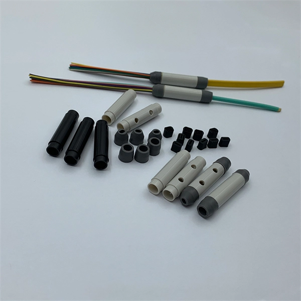
SC fiber connectors, or Subscriber Connectors, are widely used in telecom and networking for their strong performance and easy handling. They're known for a secure push-pull connection that's quick to insert and remove. These sc connectors are popular because they are versatile and. Fiber optic connectors are mechanical devices that join optical fibers with minimal signal loss, enabling high-speed data transmission. Key performance metrics include: Insertion Loss: ≤0. Unlike fiber splicing, which is permanent, connectors allow for easy connection and disconnection of cables, making them ideal for maintenance and flexibility in. While the small size of fibre optic connectors does not mean they play a minor role, the type of connector you use affects the overall efficiency of light transmission across the fibre network. A good connector: Provides low insertion loss (minimal signal attenuation). Ensures low return loss (minimal light reflection back into. Most SFP fiber optic modules use LC connectors, while SC connectors are mainly found in legacy networks and MPO/MTP connectors are used for high-density cabling rather than directly on standard SFP modules. This connector landscape reflects how modern SFP deployments prioritize port density and.
[PDF]
A fiber-optic cable, also known as an optical-fiber cable, is an assembly similar to an but containing one or more that are used to carry light. The optical fiber elements are typically individually coated with plastic layers and contained in a protective tube suitable for the environment where the cable is used. Different types of cable are used for in different applications, for exa.
[PDF]
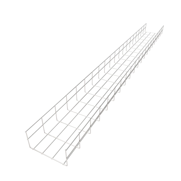
Made from recycled high strength steel or aluminum – a green solution, our trays are reusable and reclaimable. Do not require field fabrication – hand-bendable trays easily work around obstacles, or.
[PDF]

They mainly consist of optoelectronic components (such as optical transmitters and receivers), functional circuits, and optical interfaces, aiming to achieve the functionalities of optical-to-electrical and electrical-to-optical signal conversion in optical fiber communication. As an essential component of optical fiber communication, optical modules are optoelectronic devices that facilitate the conversion between optical and electrical signals during the transmission process. Operating at the physical layer of the OSI model, optical modules are core devices in optical. Modern communication networks rely on optical transceivers to transfer data at the speed of light. Whether in 5G base stations, hyperscale data centers, or long-haul telecom networks, these modules convert electrical signals into optical ones — and back again — to ensure fast, stable, and. Optical modules are compact devices that convert electrical signals into optical signals and vice versa. They are used in fiber optic communication systems to transmit data over long distances with minimal loss and interference. These modules typically consist of a laser or LED transmitter, a. That is, metal medium communication represented by coaxial cables and network cables is gradually being replaced by optical fiber media.
[PDF]

Global key players of Arrayed Waveguide Grating include NTT, NeoPhotonics, Accelink, Broadex Technologies, Agilecom, etc. The top five players hold a share over 64%. Asia-Pacific is the largest market, and has a share about 48%, followed by North America and Europe. Array waveguide gratings are important in telecommunications because they enable multiplexing and demultiplexing. Function: AWGs are used mainly for multiplexing (DWM). Operating. Arrayed waveguide gratings (AWGs) are passive optical devices based on planar lightwave circuits (PLCs) that spatially separate or combine light of different wavelengths. They utilize a phased array of waveguides with constant path length increments to create constructive interference for specific. Did you know that Arrayed Waveguide Gratings (AWGs) can multiplex and demultiplex over 100 different wavelengths of light on a single optical fiber? This makes them foundational to Dense Wavelength Division Multiplexing (DWDM), a technology that dramatically increases the bandwidth of optical. Arrayed waveguide gratings (AWG) are commonly used as optical (de)multiplexers in wavelength division multiplexed (WDM) systems. These devices are capable of multiplexing many wavelengths into a single optical fiber, thereby increasing the transmission capacity of optical networks considerably. At the transmission end, AWG arrayed. The AWG Arrayed Waveguide Gratings Module Market Size was valued at 799. 2 USD Million in 2024.
[PDF]

This article discusses the significant specifications of ADSS fiber optic cables, providing information about its structural features, mechanical performance, optical control, and environmental tolerability. One such innovation is the ADSS cable, a fiber optic solution designed to meet the demands of modern networking while providing exceptional performance and reliability. This introduction will explore what ADSS cable stands for, its key benefits, and its diverse applications across multiple. This comprehensive guide breaks down ADSS's core definition, intricate structures, unique advantages, and real-world uses, equipping you to understand why it's become indispensable for modern aerial fiber networks. What Is an ADSS Fiber Optic Cable? ADSS, short for All Dielectric Self-Supporting. ADSS (All-Dielectric Self-Supporting) fiber optic cables are specifically produced for elevated applications in electric power transmission and distribution. In this article, I want to share a complete view of ADSS fiber optic cables based on my real-world experience. All-Dielectric: All components of the cable are non-metallic materials (e., optical fibers, Fiber Reinforced Plastic, water-blocking filling compound, polyethylene sheathing, etc. Unlike traditional fiber cables that rely on messenger wires or steel reinforcement, ADSS cables are fully dielectric, making them ideal for.
[PDF]