Urban Areas: 25–40m spacing (concrete poles, 10–12m height)., steel lattice structures). Factors: Cable weight (kg/km) Ice loading (up to 50mm. The Fiber Optic Association, Inc. (FOA) was founded in 1995 to help develop the workforce to build the fiber optic networks to support a rapid expansion in communications and the Internet. The charter of the FOA was to promote professionalism in fiber optics through education, certification, and. to n utral comm. cable R. FO-CS JOINT USE CLIMBING SPACE REQUIREMENTS 51. APPENDIX A - COVER SHEET / TOC 52. RUS DRAWING #PM12 58. CHECK. d suppliers of electrical construction services. They define a minimum baseline of quality and workmanshi for installing electrical products and systems. NEIS® are intended to be referenced in contrac documents for electrical construction ation or liability to users of this publication. Choose the type of pole The basic pole height is 7m and the tip diameter is 150mm. In case of special sections, crossing obstacles or roads or railways, the pole height of 8m, 9m, etc. can be selected. Cables 300 V or less need to be a minimum two feet over the street light. Climbing Space is an unobstructed, vertical space along the side or corner of the pole. In gen-eral, it consists of an imaginary box, 30-inches square, extending at least 40 inches above the highest communications cable or.
[PDF]
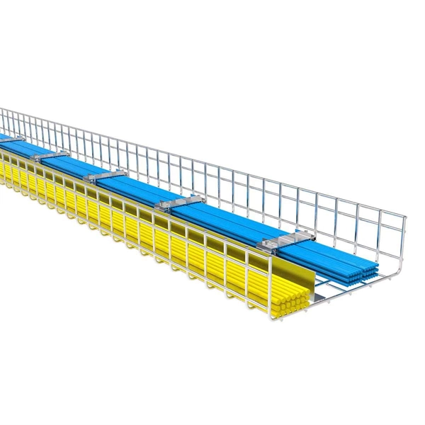
This document outlines the key requirements for cable tray layout, installation, and fireproofing in industrial and commercial environments. Route Planning and Layout Principles. Provides technical requirements concerning the construction, testing, and performance of metal cable tray systems. It is the first joint effort of NEMA and CSA International to put in one place standards for metal trays per both NEMA and CSA methods. Addresses shipping. Method Statement installation of Cable Trays and Ladders - Planning Engineer FZE. Whether you're designing a new. Below is the detailed cable tray installation method statement not only for cable tray but also applicable for GI ladder and trunking for indoor and outdoor applications and in service rooms like pump rooms, electrical rooms and plant rooms etc. All materials intended for cable tray, ladder and. Cable tray installation must comply with specific technical standards to ensure electrical safety, system reliability, and long-term maintainability. The mechanical and electrical characteristics, tests, certifications, overall quality management, recommendations mentioned in this technical guide only apply to our own cable management ranges and cannot under any circumstances be transpos regulations which.
[PDF]
Standard splice plates can often provide a safe electrical path if they are UL Classified and bolted tight. However, you must use copper bonding jumpers if the tray is painted or has expansion joints for movement. A. The intent of this article is to review grounding practices for cable tray wiring systems. The Equipment Grounding Conductor is the electrical circuit's safety conductor. When designing a cable tray. Snap Track requires only single bonding jumper. Installation Guideline: Scroll to bottom of page to view All Bonding Jumpers Cut Sheets A bonding jumper is required to be installed with adjustable splices and expansion splices. If an EGC cable is installed in or on a cable tray, it should be bonded to each or alternate cable tray sections via grounding clamps (this is not required by the NEC® but it is a desirable practice). In addition to providing an. Do I have to use a bonding jumper at each cable tray splice point that is bolted tightly together? I currently have 3 runs of 24 tray about 80ft long. we have one expansion plate section per run in which I plan on using a bonding jumper at, I am curious about all other points You aren't even. Wire mesh cable trays are widely used in commercial offices, industrial facilities, data centers, and smart building infrastructure because they provide unmatched flexibility, excellent airflow, and fast, adaptable installation. Their open-grid design makes it easy to route, add, or modify cabling.
[PDF]
Learn about the market conditions, opportunities, regulations, and business conditions in paraguay, prepared by at U. Embassies worldwide by Commerce Department, State Department and other U. agencies' professionals The standards regime in Paraguay includes obligatory and voluntary standards. The Group's environmental commitment is centred on 3 guiding lines: taking on board environmental management in the running of its industrial sites, reducing the environmental impact of its products by eco-design, providing environmentally friendly solutions that contribute to energy savings. Type. REV.
[PDF]

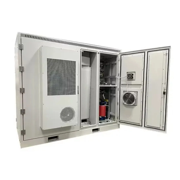
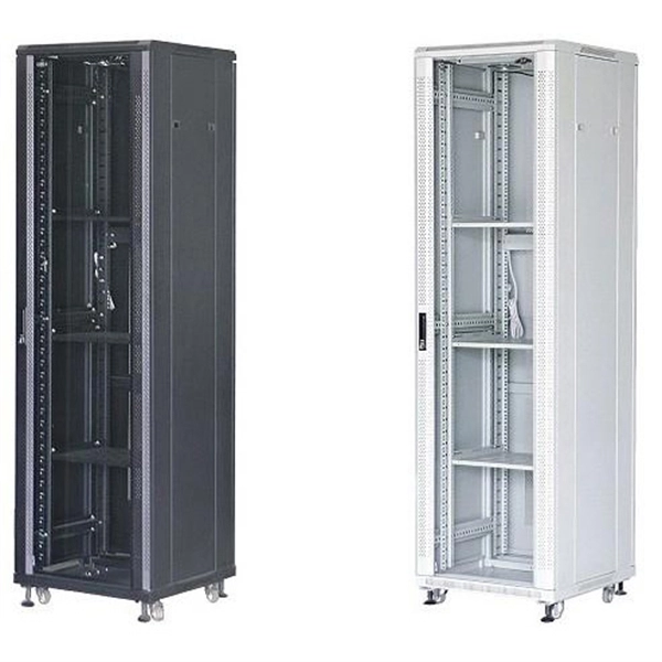
The use of locking cabinets with advanced steel and tamper-resistant designs utilizes physical barriers to limit access to sensitive materials, making them harder to reach for unauthorized individuals. This pressure can cause the gap below server cabinets, which is often 2” or more, to become an air stream between hot and cold aisles. The resulting mix of air reduces the effectiveness of a containment solution. The Cool Shield Magnetic Cabinet Skirt provides an easy fix for this issue. These. Commercial environments have evolved as technology advances, and having a robust cabling infrastructure is crucial for scalability, minimising downtime, and enhancing productivity. Educational institutions are increasingly adopting smart technologies and cloud-based resources, so the foundation of. Many network devices are stored in the cabinets. In order to meet the normal operation of these devices in the cabinets, when the computer room cabinets are full of various cabinets and devices, we need to consider how to place the network cabinets? 1. Network cabinet placement skills (1) Before. A network cabinet is defined as a physically enclosed compartment built to store networking gadgets like patch panels, modems, switches, and a multitude of cables. Network cabinets support large, modular network switches by providing additional space for cable management and side-to-side airflow solutions. Networking cabinets tend to have.
[PDF]

This guide will walk you through each stage of the compliance and permitting process for outdoor kitchens, highlighting common pitfalls, must-follow codes, and tips for smooth project approval. Barbecue grills shoved into a corner of the deck have evolved into full-blown outdoor kitchens. As a “code guy,” I should point out that the International Residential Code (IRC) has a few things to say about kitchens, and it doesn't care if the kitchen is inside or outside the house. The gas pipe. Building your dream outdoor kitchen is an exciting project, but it's essential to understand the outdoor kitchen code requirements in your area. These codes vary by location and typically cover aspects like electrical, plumbing, and construction standards. Building an outdoor kitchen can transform your backyard into a functional and attractive space for cooking and entertaining. Who can resist the aroma of food cooking. Building an outdoor kitchen is not as simple as setting up a barbecue and a countertop—there are legal, safety, and logistical hurdles that, if ignored, can lead to costly fines, project delays, forced teardown, or even safety hazards down the line. Many homeowners are surprised to discover that. Installing an outdoor kitchen is one of the most desirable upgrades for homeowners who want to make the most of their backyard.
[PDF]

Provides technical requirements concerning the construction, testing, and performance of metal cable tray systems. It is the first joint effort of NEMA and CSA International to put in one place standards for metal trays per both NEMA and CSA methods. Addresses shipping. Cable trays play a vital role in supporting electrical cables and wires in commercial, industrial, and utility installations. For proper installation, design, and maintenance, adherence to international standards is essential. One of the most recognized frameworks globally is the IEC standard for. association representing the major electrical equipment manufac-turers in the U. The Cable Tray ng standards, performance standards, test standards and application in this document have been tested extens ompetent professional en completely installed, without damage either to conductors or. CABLE TRAYS THE GLOBAL SPECIALISTIN ELECTRICAL AND DIGITAL BUILDING INFRASTRUCTURES TECHNICAL GUIDE Not all cable trays are equivalent. The mechanical and electrical characteristics, tests, certifications, overall quality management, recommendations mentioned in this technical guide only apply to. Not all cable trays are equivalent. For those of you that have experience working with cable tray systems, you have probably noticed the high-level of influence NEMA has in guiding cable tray management projects.
[PDF]

This section applies to grounding of transmission and distribution lines and equipment for the purpose of protecting employees. Note to paragraph (a): This section covers. Correct grounding of services depends upon understanding the definition and role of the grounded conductor. The neutral conductor is typically the grounded conductor connected to the system's neutral point, carrying current under normal operation. Grounding electrode conductors must be connected at. Learn the grounding and bonding rules when powering two or more buildings or structures in the same area with a single service. To catch up on Lorenzo Mari's series on National Electrical Code 2023 Basics: Grounding and Bonding, follow these links: NEC's Section 250. Bonding is connecting things together with a conductive path to establish electrical continuity. Both are foundational safety concepts in the NEC, and. NFPA 70: National Electrical Code Article 250 covers the minimum requirements for grounding and bonding and, although the NEC lists requirements to abide by, it should not be taken as a design manual. Some terms and requirements discussed may be true for the European standards, however, the intent.
[PDF]
When designing a cable tray wiring system, the designer should evaluate the National Electrical Code's (NEC) Equipment Grounding Conductor (EGC) options that are applicable for the project. Use the cable tray as the EGC. The metal in cable trays may be used as the EGC as per the limitations. Cable tray grounding wire is the safety connection that links your electrical system's cable tray to the ground. This provides a safe path for any stray electrical currents to flow safely into the earth, avoiding damage to your equipment and reducing the risk of electric shocks. It involves connecting cable trays to the facility's grounding system, providing a low-impedance path for fault currents and protecting personnel.
[PDF]

Learn how to connect equipment grounding conductors to receptacles and keep their continuity in boxes. Sometimes if I have a 3 or 4-gang plastic nail-on switch box that has a bunch of NM cables, when I'm making up the box rather than using a big blue wire-nut for my grounds I'll separate the grounds into 2 groups and use red/tan wirenuts instead, especially if there's 2 circuits in the box. I can. In a metal box, a wire type equipment grounding conductor can be attached to the box with a ground screw or clip and terminated to the switch or receptacle in the box. Connecting the receptacle grounding terminal to the metal box ensures an effective ground-fault current path. The basic rule achieves this through an equipment grounding jumper; four exceptions. I'm using metal box has two ground screws, can I wrap around one ground wire (from supply side) on one of ground screws then connect it to the outlet and connect another ground wire (or two wires ) going to the next box (es) on the secondary ground screw? I know pig-tail method is probably better. Electrical boxes play a crucial role in housing and protecting electrical connections, ensuring safety and functionality. Among the various types of wires found in an electrical box, the ground wire is of paramount importance. It provides a path for electricity to safely flow to the ground.
[PDF]

Recommendation ITU-T L. 101 describes characteristics, construction and test methods of optical fibre cables for buried application. 0, in February 2016. First, in order to demonstrate sufficient performance of an. ion) and “ Installed” (after installation). The following formulas may be used to determine general guidelines for installing Corning Optical Communications fiber optic cable; however, refer to the cable specifi simply double the minimum working bend radius. Split cable guides and split 40-in. 1. The methods described are intended for guideline use only, as it is impossible to cover all the various conditions that may arise during an installation. Individual. The Fiber Optic Association, Inc. (FOA) was founded in 1995 to help develop the workforce to build the fiber optic networks to support a rapid expansion in communications and the Internet. The charter of the FOA was to promote professionalism in fiber optics through education, certification, and. Home / Instruction Sheets / Fiber Optic Cable Direct Burial Guidelines Need Help?. When planning a fiber optic network installation, one of the most common questions is: How deep are fiber optic cables buried? Proper burial depth is critical for the safety, durability, and performance of your communication infrastructure.
[PDF]