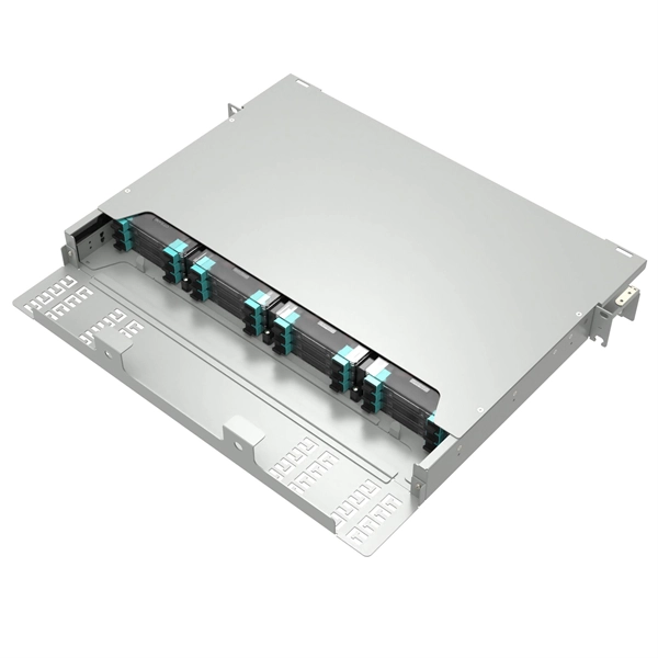
DR (Distance Range): Up to 500 meters, using single-mode fiber for inter-data center links. An SFP (Small Form-factor Pluggable) module transmits data over fiber using specific wavelengths and power levels, which directly influence how far the signal can travel before degradation occurs. This is why two. Optional bend insensitive single‑mode optical fibers have a lower index of refraction material surrounding the fiber that reflects light back into the core and are recommended when the optical fibers or cables have to support bend radii less than 1 in (25 mm). Single‑mode optical fiber connectors. Single-mode fiber uses a 9/125 µm core/cladding structure that supports only one propagation mode, which minimizes modal dispersion and allows signals to travel tens of kilometers with low attenuation. Multimode fibers have larger cores (typically 50/125 µm or 62. 5/125 µm) and support multiple. In fiber-optic communication, a single-mode optical fiber, also known as fundamental- or mono-mode, is an optical fiber designed to carry only a single mode of light - the transverse mode. Modes are the possible solutions of the Helmholtz equation for waves, which is obtained by combining. This document outlines the specifications for a single-mode optical fiber and cable designed for use around the 1310 nm zero-dispersion wavelength, suitable for both the 1310 nm and 1550 nm regions, and compatible with analogue and digital transmission.
[PDF]
This integration is achieved through the use of wavelength division multiplexing (WDM) filters, which separate the transmit and receive wavelengths within the same fiber. These modules play a vital role in transmitting and receiving optical signals. TOSA ( Transmitter Optical Sub-Assembly), converts electrical signals into optical signals for transmission. In this mode, the WDM system transmits multi-wavelength optical signals in receive and transmit directions through separate fibers. Simple design and low requirements. If you're dealing with data centers, telecommunications, or AI networking, grasping the key parameters of an optical. In the era of 5G, AI, and high-speed data centers, optical modules serve as the core bridge for converting electrical signals to optical signals (and vice versa), enabling fast, reliable data transmission across networks. Among various optical module form factors, SFP (Small Form-Factor Pluggable). Fiber optic transceivers are key components of the fiber optic transmission network. They are designed in small form-factor with some integrated optical sub-assemblies which can be suitable for the high-density network. There are many SFPs available in the market with different features and. Most systems operate by transmitting in one direction on one fiber and in the reverse direction on another fiber for full duplex operation.
[PDF]
These modules are designed to transmit 100G Ethernet signals across single-mode fiber over distances up to roughly 80 kilometers. The “BiDi” concept, short for bidirectional transmission, means that a single fiber strand carries traffic in both directions using different. The 80km SFP is a compact, hot-pluggable optical transceiver module standardized for long-distance fiber optical communication, with a maximum single-fiber transmission distance of 80 kilometers as its core performance indicator. It is designed to meet the interconnection needs of medium and. SFP (Small Form-factor Pluggable) modules have evolved beyond short-reach Ethernet, enabling reliable 80km and 120km links with optical performance, wavelength management, and power efficiency. This guide dives into the practicalities of 80km and 120km long-haul SFP modules, including key. It can reach up to 80km using single-mode fiber. This module is small and easy to swap. You can change it without turning off your network. The QSFP28-100G-ZR4 uses LAN-WDM technology. It sends many signals through one fiber. This makes your network. Cisco ® QSFP28 100G ZR extends 100GbE coherent links from QSFP28 ports reaching up to 80km over dark fiber and up to 300km over amplified Dense Wave Division Multiplexing (DWDM) links.
[PDF]

Small Form-factor Pluggable (SFP) modules are a cornerstone of modern high-speed networks, enabling flexible, hot-swappable fiber connections in dense deployments. This article reviews reliability, testing practices, and real-world considerations from a QA and MTBF perspective. We explore. Add Judgment Criteria of Reliability Test Results, vulcanizing Corrosion requirement and airborne Contaminants Test. Make some editorial modifications. 5 Stress Test Requirements for Optical Module Components. ABSTRACT: The Optical Internetworking Forum (OIF) has been instrumental in standardizing coherent optics at the physical layer, with the 400ZR implementation agreement (IA) being a significant achievement. This white paper reports on the performance evaluation of 400ZR and OpenZR+ pluggable modules. Linear pluggable optics have emerged as a transformative technology in the telecommunications and data center industries, representing a significant evolution from traditional transceiver architectures. This technology enables direct fiber-to-chip connections without the need for intermediate. Long Term Reliability Methodology of Next Gen Pluggable Optical Modules for PAM4 Applications in Hyperscale Datacenters V. The coherent optics landscape has gradually transitioned from engineered links on closed systems to today's multi-vendor, standards-driven ecosystem.
[PDF]

A lighting control module operates as the central controller for a lighting system. It receives input from switches, apps, or sensors and regulates electrical flow to connected lights. Depending on the setup, it adjusts brightness, color temperature, or full lighting scenes. It acts as a bridge between your physical lighting fixtures and the smart systems that manage them. Instead of relying solely on traditional wall switches, you can control your lights via remotes, mobile or web apps. A lighting control module is an essential component in a lighting control system that manages how lights are powered, dimmed, or switched on and off. Think of it as the “brain” that receives commands—either from a manual switch, a sensor, or a building automation system—and translates them into. A lighting control module is a smart device that manages lighting circuits, adjusting brightness, automating schedules, and responding to sensors. It enhances comfort, efficiency, and ambience in homes and commercial spaces. Explore the multifaceted benefits and applications of lighting control modules, from home automation to industrial. These modules are designed to communicate with various sensors, switches, and control panels, making lighting adaptable to different environments and user preferences. It enables precise management of lighting systems, allowing for adjustments in brightness, color, timing, and even integration with other smart devices. This innovation.
[PDF]

A 630A MCCB means the breaker is rated to handle up to 630 amperes of continuous current without tripping under normal conditions. This type of MCCB is commonly used in industrial power distribution panels, commercial buildings, and large electrical systems where higher current. A Molded Case Circuit Breaker (MCCB) is a protective device designed to automatically disconnect electrical circuits during overloads or short circuits. This type of. This ComPacT NSX630N is a complete 3P 3d fixed circuit breaker designed to optimize space and breaking capacity. It is an optimal choice for all standard and specific applications. The breaking capacity (Icu) is 50kA rms at 415VAC 50/60Hz. This product. Fuji Molded Case Circuit Breakers are more compact (especially 100A, 125A, 250A frames) than any breakers on the market, so they take up less space in control panels. U denotes non-interchangeable trip unit. With a 630A frame rating and adjustable settings from 400A to 630A, it offers flexible protection for high-power applications. Ir = 300 - 630A; Icu = Ics = 65kA at AC 440V How to request a quotation How can I request a quotation for more than one product? (Watchlist). GENLITEC POWER® GTS630 630A Automatic Transfer Switch (ATS) Panel is designed for seamless and automatic power switching between the main utility supply and backup generators. Engineered for high-power applications, this ATS ensures uninterrupted power supply, reducing downtime and enhancing.
[PDF]

In this video, we'll walk you through the process of wiring a home distribution box with a detailed connection diagram. Whether you're an electrician or a DIY enthusiast, this guide will help you understand the basics of home electrical distribution. more Welcome to our channel! In this video. A distribution box is the heart of any electrical system. It takes the incoming power and safely distributes it to different circuits throughout your building. However, the key to. Material preparation: Prepare the required circuit breakers, wires, wiring ties and other materials, and ensure that they meet the design drawings and installation requirements. Location determination: Determine the installation position of the circuit breaker according to the position of the. In modern electrical systems, cable distribution boxes (also known as electrical distribution boxes or distribution boxes) play a crucial role as the key hub for managing, distributing, and protecting circuits. Whether it is residential buildings, commercial facilities or industrial sites, the. Hey, in this article we are going to see the Single Phase Distribution Box Wiring Diagram and Connection Procedure. A distribution board or distribution box is where the main power supply is distributed to multiple loads.
[PDF]

These numerical codes, ranging from 1 to 99, uniquely identify the functions of protective relays, associated devices, and control equipment in electrical power systems. In electric power systems and industrial automation, ANSI Device Numbers can be used to identify equipment and devices in a system such as relays, circuit breakers, or instruments. The device numbers are enumerated in ANSI / IEEE Standard C37. 2 Standard for Electrical Power System Device Function. According to the ANSI/IEEE standards, device function numbers are crucial identifiers in power system protection and control engineering. ANSI IEEE Standard Device Numbers are below: (the more commonly used ones are in bold) 86T is a Lockout Relay for a. The widely used United Sates standard ANSI/IEEE C37. Even in those parts of the world where IEC standards are predominate, the use of ANSI numbering. For power grid systems, ANSI and IEEE functional number codes dictate the use and restrictions of both the devices themselves, as well as the functions of those devices within the scope of a circuit. These devices include switches, disconnects, circuit breakers, generators, and motors. Instead of verbal descriptions, we use numbers to describe the functions of a relay. Why use numbers instead of words? Efficiency.
[PDF]

In this video, we'll walk you through the process of wiring a home distribution box with a detailed connection diagram. Whether you're an electrician or a DIY enthusiast, this guide will help you understand the basics of home electrical distribution. more Welcome to our channel! In this video. An electrical panel box, also known as a breaker box or a distribution board, is a crucial component of any electrical system. It serves as a central hub for distributing electricity throughout a building, ensuring that power is delivered safely and efficiently to all the required locations. Distribution Board or DB is an electricity supply system or a common enclosure that distributes the electrical power feed into subcircuits. It includes isolator, RCCB (Residual current circuit breaker) or RCD (Residual-current device) devices, protective fuses or MCB's (Miniature Circuit Breaker). Learn how to install a distribution box safely and correctly. Covers wiring, placement, standards, and expert tips for a compliant setup. It takes the incoming power and safely distributes it to different circuits throughout your building. Box installation: Make sure that Distribution box has been correctly installed and fixed. Material preparation: Prepare the required circuit breakers, wires, wiring ties and other materials, and ensure that they meet the design drawings and installation requirements. To understand how a breaker box works, it is helpful to.
[PDF]

It's important to watch the supply reel while installing to ensure the minimum bend radius isn't compromised. Use proper cable pulling lubricants. Sequentially mark the pulling role for easy identification. Use extreme caution when removing the pull eye. Fiber optic cable is surprisingly strong, durable and pliable; however, several best practices should be followed to ensure a successful cable installation. This article explores recommendations for pulling and installing fiber optic cable. Most fiber optic cables boast a pull strength of 100 – 200. That's where investing in high-quality patch cords makes a real difference—they arrive with better polishing, protection caps, and lower insertion loss, reducing the margin for error during deployment. When discussing installation mistakes, endface contamination deserves special attention because. Fiber optic troubleshooting is an essential skill for network administrators, technicians, and engineers responsible for maintaining and repairing fiber optic systems. These high-speed, high-capacity communication networks are increasingly replacing copper cables, offering superior performance and. Harnessing the full potential of fiber optics hinges greatly on the quality of its installation. During installation, all curvatures should be smooth. The cable should be bent as little as possible. Most fiber damage does not come from normal operation after the system is live.
[PDF]

A simple 1-core FTTH drop cable costs around $0. 13 per foot, while a 288-count optical fiber cable for building backbones can reach $6 per foot or more. In this article, we'll take a closer look at the main parameters determining the price of a fiber patch cord, provide up-to-date pricing ranges, and assist you in becoming a smarter buyer—regardless of whether you are making a purchasing decision for a project, replenishing inventory, or placing an. Check each product page for other buying options. Need help?. Fiber-optic cable materials typically cost $1 to $6 per linear foot, depending on fiber count and cable type. Commercial building installations with 100-200 network drops generally range from $15,000 to $30,000. Single-mode fiber costs less per foot than multimode fiber, but it requires more. Knowing how much fiber optic cable costs, which factors can impact cost, and key cost considerations can help you avoid unnecessary expense and get the most out of your budget. First. Get low-loss fiber patch cables & cords with various connector options that support fiber optic cabling up to 400G. Customized cables available. Main cost drivers include cable grade (indoor vs outdoor, armoured), distance, and labor for trenching, splicing, and termination. This guide presents ranges in USD and practical price estimates to help.
[PDF]

Since there are two sections, separated by a circuit breaker, the fault on one section does not interrupt the other section of the bus. Maintenance of the bus section can be done individually, without affecting other. Variants include a sectionalized single bus, where one or more bus couplers divide the bus into segments to limit the extent of outages. Layout: one energized bus; each feeder/generator/transformer bay has a breaker and isolators. Sectionalization adds a bus coupler breaker and isolators to split. The relevant standard for High Voltage Switchboards is 62271-200. This standard covers High Voltage Switchboards with voltage levels above 1kV and up to 52kV. It is also used in small outdoor stations having relatively few outgoing or incoming feeders and lines. shows the single bus-bar system for a typical power station. The generators, outgoing lines and. Bus-bars are copper rods or thin walled tubes and operate at constant voltage. We shall discuss some important Bus Bar Arrangement in Power Station and sub-stations. All the diagrams refer to 3-phase arrangement but are shown in single-phase for simplicity. Single Bus-bar System: The single. This is a single bus system, with additional circuit breaker and isolators, making two different sections of bus, hence called a single bus system with bus sectionalizer. A busbar is a metal bar, usually made of copper or aluminum, that carries electricity inside switchgear.
[PDF]

It operates by emitting a bright and visible red laser light into the fiber and detecting the location of faults by observing the light leaking out of the fiber. It is also possible to locate faults in OTDR dead zones and perform fiber identification from one end to the other. When it comes to testing fiber optic cables, a Visual Fault Locator (VFL) is an essential tool in your toolkit. It's a cost-effective and. Whether you're a seasoned technician or a fiber enthusiast, a VFL is the first step to make your life easier in troubleshooting a fiber optic cabling issue. We will be explaining what The VFL's primary purpose is, and how best to use it. Below are some key use cases for a VFL. It gives instant visual proof of where light escapes the fiber. Even beginners can spot bends, cracks, or bad splices without complex tools. A visual fault locator saves time, cuts stress, and reduces repeat work., optical fiber fault detector, optical fiber fault test pen) is a 650nm (± 20nm) semiconductor laser as a light-emitting device, which emits stable red light through a constant current source drive, and connects with the optical interface into the optical fiber, so. In the world of fiber optic communication, diagnosing and troubleshooting network issues is essential to maintain smooth connectivity. Whether you are a beginner or a professional working with fiber optics.
[PDF]