
The mounting height of a network rack typically ranges from 24 inches to 84 inches (2 to 7 feet), depending on the equipment and installation requirements. A server rack is more than just a physical frame—it determines how well your rack servers, network switches, PDUs, and storage arrays can be organized, cooled, and maintained. Selecting the right rack size ensures not only compatibility with today's hardware but also room for future expansion. The. Common server rack sizes are 19‑inch width, heights like 42U or 48U, and depths from ~24″ to 48″. Choose size based on equipment type, cooling, space, and future growth. Most IT environments default to 42U, 19-inch width, and 1000–1200 mm depth unless space constraints or special equipment dictate. A rack unit, abbreviated as “U,” is the standard unit of measurement for the height of devices designed for rack mounting. One rack unit equals 1. Important: U describes height only, but a server's real "capabilities" are also determined by chassis depth, internal layout, airflow, rails, power, and expansion (PCIe/risers, NVMe. You'll get precise, vendor-agnostic dimensions for standard server rack sizes—including exact width (19″ internal / 24″ external), height (42U = 73. 5″), depth (24″–48″), and the universal 1U = 1. 75″ rule—plus how to verify usable space, avoid common fitment errors, and select based on equipment.
[PDF]

See this topic to learn how to remove and install a door. Unlock and open the door. Removing a door Hold the door in place, and lift both hinge pins until they lock in the open position so that the door is disengaged. Remove the door from the rack cabinet frame. Install. Before installing your server in a rack cabinet, review the following guidelines: Two or more people are required to install the device in a rack cabinet. Ensure that the room air temperature is below 35°C (95°F). Do not block any air vents; usually 15 cm (6 in. ) of space provides proper airflow. In this comprehensive guide, we will walk you through the step-by-step process to ensure a successful installation and setup of your network cabinet system. Key steps include measuring the installation area, mounting rails, organizing cables, and testing stability. Proper grounding and compliance with safety. Page 3 M3. Click Side Panels (E) into place. To install the Tempered Glass Door (G), locate the side with two pins. With your thumb, pull down on the spring pin and slide it. Complete Assembly Procedure for 9U Wall Mounted Network Cabinet (Double Section) How to assemble a double section wall mounted network cabinet server rack? 1, Insert top and bottom panels into the side frames. And fixed the frame on the front door position with 4 M5*8 self-tapping screws.
[PDF]

The system cover is off or incorrectly installed. The intrusion switch might be triggered or not working. In this scenario at least one fan or fan assembly (contains two fans) is either damaged (connector, fan blade, fan blade frame), missing or failed. Check the front LCD or system event log to. What do the BMC logs say? Does the server overheat? Are the fans just off because it's not under load? what kind of server do you have, give a spec sheet. Server fans maintain critical airflow to prevent component overheating and system failures. (Adapted from hardware diagnostic methodologies in service docs) 💡 *Pro Tip: Replacing bearings extends fan life by 2-3 years at 20% of new fan cost* (Cost data from “Dell & HPE Server Repair Services. we've got 3 Dell PowerEdge R6615 with an AMD Epyc 9174F in it and the fans are doing something weird. Most of the time they are at 8-9k RPM and fairly quiet. But every minute or 2 they are revving up to full speed (~ 24k) or half speed (~ 13k) and then back down. From failed capacitors to deep grime hiding in your rotor shaft — I show you how to diagnose each fault step-by-step using. Server racks can get hot fast. When the heat isn't managed well, it can slow down your servers, cause shutdowns, or even damage your equipment. Over time, this.
[PDF]

There are several types of outdoor server racks, each tailored to specific environmental and operational needs. The two primary categories based on structural design are seismic and non-seismic racks. Free Standing 19' 32U 600x600mm. Ecoline Server Cabinet Flat Pack RAL 9005 black W/ 4 fans L Type Support Slide Rail, Enclosure Depth=600mm. For outdoor server and network applications, the weatherproof rack cabinet is designed to protect equipment from water, environmental elements, and debris. With front and rear doors, allows easy access for installation and maintenance while the o-ring around each door creates a water resistant seal. We Provide outdoor cabinet range provides single or multi-chamber, temperature controlled secure environment for valuable sensitive communications, electronic & electrical equipment, in a cost effective and space saving manner. Designed to house a variety of communications equipment and incorporated design flexibility to. Check each product page for other buying options. At Sturdx, we provide outdoor cabinets that merge resilience, functionality, and reliability. This guide delves into the features, benefits.
[PDF]

This guide walks you through the complete fiber installation process, from checking availability to optimizing your Wi-Fi network performance. Upgrading to fibre internet involves replacing your existing copper cables with new fibre-optic ones. This upgrade brings faster speeds and more reliable connectivity. Here is what the installation process is like: One of our technicians will visit your home, remove the old copper wiring and. If you need Fiber Optic Cable Installation in Malta or areas close by allow us to assist you by connecting you with specialized pros who can do the work you request. Step 1: Planning Before any installation begins, thorough planning is essential. This includes determining the network's requirements, such as bandwidth, distance, and the number of. This guide will explain the entire set of activities involved in installing Fiber optic cable contractors -from the early planning stage right through testing-for facility managers, IT teams, and low-voltage contractors to build high-performance networks safely and efficiently. The processes. The Fiber Optic Association, Inc. (FOA) was founded in 1995 to help develop the workforce to build the fiber optic networks to support a rapid expansion in communications and the Internet. The charter of the FOA was to promote professionalism in fiber optics through education, certification, and. We offer :- For more information email us on sales@merlin.
[PDF]

These numerical codes, ranging from 1 to 99, uniquely identify the functions of protective relays, associated devices, and control equipment in electrical power systems. In electric power systems and industrial automation, ANSI Device Numbers can be used to identify equipment and devices in a system such as relays, circuit breakers, or instruments. The device numbers are enumerated in ANSI / IEEE Standard C37. 2 Standard for Electrical Power System Device Function. According to the ANSI/IEEE standards, device function numbers are crucial identifiers in power system protection and control engineering. ANSI IEEE Standard Device Numbers are below: (the more commonly used ones are in bold) 86T is a Lockout Relay for a. The widely used United Sates standard ANSI/IEEE C37. Even in those parts of the world where IEC standards are predominate, the use of ANSI numbering. For power grid systems, ANSI and IEEE functional number codes dictate the use and restrictions of both the devices themselves, as well as the functions of those devices within the scope of a circuit. These devices include switches, disconnects, circuit breakers, generators, and motors. Instead of verbal descriptions, we use numbers to describe the functions of a relay. Why use numbers instead of words? Efficiency.
[PDF]

The optical power meter is similar to the voltohmmeter in application but measures the optical resistance (losses measured in dBm or dBM) of a cable before and after installation and provides a comparative analysis of the splices. The range of the meter is adjustable. Regularly testing fiber optic cables helps minimize network downtime, lengthens the network's longevity, reduces maintenance requirements, and helps support network reconfiguration and upgrades. These factors significantly add to the fiber optic network's long-term performance, manageability, and. Several types of tests are commonly conducted to assess and maintain the health of fiber optic networks. Continuity testing verifies that the fiber is intact and that light can pass through from one end to the other without any blockages. These test procedures assess the physical and functional qualities of fiber optic cables, connectors, and the network as a whole. Key tests include: Effective fiber testing utilizes advanced tools such as Optical. One way to test a splice is to use an Optical Power Meter. As the components like fiber, connectors, splices, LED or laser sources, detectors and receivers are being developed, testing confirms their performance specifications and helps. Regular testing of fiber optic cables is not just a preventive measure; it's an investment in the longevity and efficiency of your network. By identifying potential issues early, you can enhance.
[PDF]
This wikiHow article will teach you how to splice a cut fiber optic cable back together with a fiber optic stripper and cutter and a fiber optic crimper. Trim off any frayed or damaged ends of the cable. While a cut or damaged fiber optic cable can temporarily take your network down, it is possible to quickly fix the cable with the right tools. When fiber cables sustain damage, specialized repair techniques help restore connectivity and maintain data integrity. This comprehensive guide outlines professional fiber optic repair protocols that align with industry best practices. Adhering to precise methodologies, we can mend impaired cables. Get your fiber optic cable repair tools together. You'll need strippers, cleavers, splice trays, a splicing machine, and cleaning materials like alcohol wipes. Leave some extra cable before the damage point. It makes cutting and splicing easier. However, you don't need to panic! It can still be fixed. If you have the right tools and knowledge, you can definitely find the solution. Understanding the causes and types of fiber optic cable damage helps detect. Whether you're a network technician, IT professional, or telecom operator, you'll find practical steps, tools, and tips to restore connectivity with minimal loss. Dekam Fiber's state-of-the-art solutions, including our UltraRepair kits, make these processes accessible and reliable.
[PDF]
In this guide, we'll break down the key wiring layout, main control panel components, and how everything connects — from the main power isolator to the PLC and sensors on the production line. Every roll forming machine relies on a precisely designed electrical control and wiring system. This system ensures that motors, sensors, drives, and. This guide will walk through the key points you need to consider when preparing electrical schematics and wiring diagrams for a roll forming machine. This guide breaks down the entire electrical system of a modern roll forming machine — from incoming 3-phase supply to flying shear synchronization — with: A complete roll forming electrical system contains: Roll forming machines are typically built for: Voltage mismatch damages VFDs, transformers. Electrical design is the backbone of any roll forming line. Electrical design is the backbone of any roll forming line. These machines convert metal coil.
[PDF]
To identify a pin, you can either enter its part number or its colors and you will be shown its pin gauge, gender, range, crimp, locator, and matching connectors. You can also choose one of the connectors from the list and see its matching pins. This diagram shows. By looks: Click the "Quick-pick" tab at the top left. Scroll through the pictures. Click on the one that looks like yours. Continue selecting items until you reach the correct class of components. By basic characteristics:. This m39029 pin finder allows you to identify a pin or connector and give you information about it and matching connectors and pins, respectively. The pinout configuration defines the order of the pins and the purpose of each pin, such as power supply, ground, or signal input/output. The. Find local businesses, view maps and get driving directions in Google Maps. Here's a useful rule of thumb: if there's room for something to fit into it, it's generally a receptacle. On the other hand, plugs are a bit harder to insert something into, so they usually. Hello Frank, Thank you for contacting Digikey, parts that are in Automotive, medical as well as other area use special connectors in this case they are similar to back plane connectors, but I do not show any that match up to work for you. I am sorry but you be better locating this part at a.
[PDF]

These boxes are designed in such a way that they can significantly reduce the risk of the flame getting outside of the box and igniting the atmosphere where flammable vapor, gases and dust particles are present. Explosion proof distribution boxes and electrical enclosures are critical components for ensuring safety in hazardous environments. They are designed to contain internal explosions and prevent ignition of surrounding flammable gases or dust. In this article, we will explore three key aspects:. Options range from Ex d (flameproof enclosure) to Ex e (increased safety) and Ex i (intrinsically safe) right through to Ex p (pressurized housing), as well as combinations of different explosion-protection types – always bearing in mind the most efficient solution for your application. These enclosures house varying electrical components such as: terminal blocks, switches, transformers, relays and other arching & sparking devices. Every connection, wire, and junction must be protected against ignition sources—and that's where the explosion proof junction box comes in. For electricians, engineers, and safety managers working in petrochemical plants, refineries, and manufacturing facilities, selecting the right explosion proof. Explosion-proof distribution panels are vital components in hazardous industrial environments, ensuring safety by preventing electrical equipment from igniting flammable gases or dust.
[PDF]

It operates by emitting a bright and visible red laser light into the fiber and detecting the location of faults by observing the light leaking out of the fiber. It is also possible to locate faults in OTDR dead zones and perform fiber identification from one end to the other. When it comes to testing fiber optic cables, a Visual Fault Locator (VFL) is an essential tool in your toolkit. It's a cost-effective and. Whether you're a seasoned technician or a fiber enthusiast, a VFL is the first step to make your life easier in troubleshooting a fiber optic cabling issue. We will be explaining what The VFL's primary purpose is, and how best to use it. Below are some key use cases for a VFL. It gives instant visual proof of where light escapes the fiber. Even beginners can spot bends, cracks, or bad splices without complex tools. A visual fault locator saves time, cuts stress, and reduces repeat work., optical fiber fault detector, optical fiber fault test pen) is a 650nm (± 20nm) semiconductor laser as a light-emitting device, which emits stable red light through a constant current source drive, and connects with the optical interface into the optical fiber, so. In the world of fiber optic communication, diagnosing and troubleshooting network issues is essential to maintain smooth connectivity. Whether you are a beginner or a professional working with fiber optics.
[PDF]

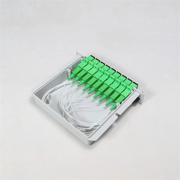
In this step-by-step tutorial, learn how to splice fiber optic cables like a pro — perfect for telecom technicians, network engineers, and field techs. more 🔧 Watch a real-time fiber optic splicing demo in action!. Fiber cable splicing is a critical step in building reliable fiber optic networks. Whether in data centers, telecom rooms, or outdoor FTTx deployments, proper splicing inside a fiber enclosure ensures low signal loss, long-term stability, and easy maintenance. This guide explains what fiber cable. In this guide, we cover the basics of fiber optic splicing, how to perform splicing using two different methods, and finally some best practices to perform good fiber splicing. What is Fiber Optic Splicing and Why is it Needed? – #1. Whether repairing a broken cable or extending a fiber run, fiber optic splicing ensures light signals travel. Regardless of your level of experience, creating high-quality, high-performance fiber optic networks requires developing your skills in fusion splicing. This guide reveals the secrets to fusion splicing with little fluff—just proven, straightforward techniques refined from years of work in the.
[PDF]
